Visual compensation system and optometric binocular device

a binocular device and visual compensation technology, applied in the field of optometry, can solve the problems of unfavorable patient care, unfavorable patient care, and substantial bulk and weight of objects

Active Publication Date: 2016-11-17
ESSILOR INT CIE GEN DOPTIQUE
View PDF2 Cites 15 Cited by
  • Summary
  • Abstract
  • Description
  • Claims
  • Application Information

AI Technical Summary

Benefits of technology

[0019]Moreover, it will be noted that the variable spherical power especially makes it possible to compensate for the spherical power created by the association of the optical elements of cylindrical power, either in order to cancel it out, or in order to obtain in total (for the complete system) a spherical power in accordance with the desired spherical power. Thus, the spherical power induced by the combination of the first optical element and the second optical element may be at least in part compensated for by the lens of variable spherical power.
[0021]This system furthermore allows the Jackson-cross-cylinder function to be provided by rapid rotation of the two optical elements of cylindrical power. To provide this function (frequently used in refraction protocols), a crossed bicylinder composed of two plane-cylindrical lenses of perpendicular axes and of opposite signs and identical powers are used. Its spherical power is zero, it is used to very rapidly vary the value of the cylindrical power by rotating the bicylinder. This rapid variation is achievable here without addition of supplementary optical elements, by driving the first optical element and the second optical element to rotate in concert.
[0028]The control signals sent to the motor will thus take into account the orientation of the visual compensation system, for example in order to compensate for power effects induced in the liquid lens due to gravity.
[0032]Such mechanisms allow the output speed of the motor to be decreased. The visual compensation system thus has a particularly fine resolution and the parameters S, C and α, that define the correction of the system may thus have an almost continuous set of values in the aforementioned ranges. In addition, by virtue of such mechanisms, the cogs, and therefore the optical elements borne by these cogs, are maintained in position even in the absence of a power supply to the motors. The optical elements (i.e. the first optical element, the second optical element and the lens) are thus mounted (in the visual compensation system) so that they (each) preserve their respective setpoint positions (even) without supply of electrical power.
[0040]The aforementioned control element (for example by means of its aforementioned computing machine) may be designed to generate at least one control signal, addressed to the third motor, depending on at least one of said setpoints and on a temperature datum generated by the temperature sensor. It is thus possible to compensate for variations in the spherical power of the lens of variable spherical power due to any variations in temperature.

Problems solved by technology

This solution is impractical and requires trial lenses to be stored separately in dedicated boxes.
It furthermore involves lens changes, resulting in undesired and non-continuous transitions in corrective power.
However, it will be understood that such an object has a substantial bulk and weight related to the number of lenses placed on each disk.
In addition, the field of view through the phoropter is limited (tunnel effect) because of the plurality of lenses that are aligned in order to obtain various correctional values.

Method used


Image

  • Visual compensation system and optometric binocular device
  • Visual compensation system and optometric binocular device
  • Visual compensation system and optometric binocular device

Examples


Embodiment Construction

[0049]The description which follows with regard to the appended drawings given by way of nonlimiting examples will clearly elucidate the essence of the invention and the manner in which it may be carried out.

[0050]In the appended drawings:

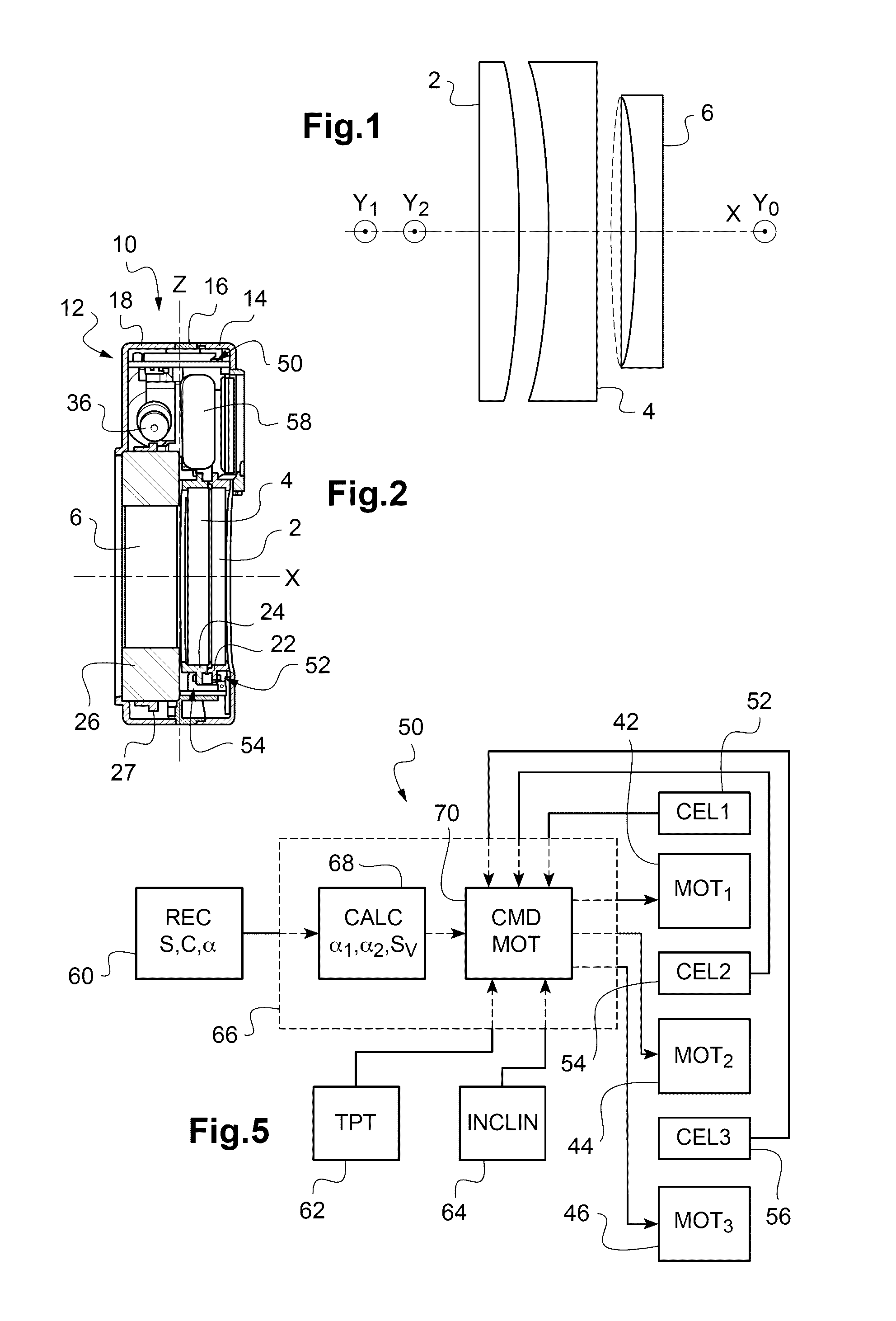
[0051]FIG. 1 schematically shows the optical elements used in one exemplary implementation of the invention;

[0052]FIG. 2 shows a cross-sectional view of an exemplary visual compensation system according to the teachings of the invention;

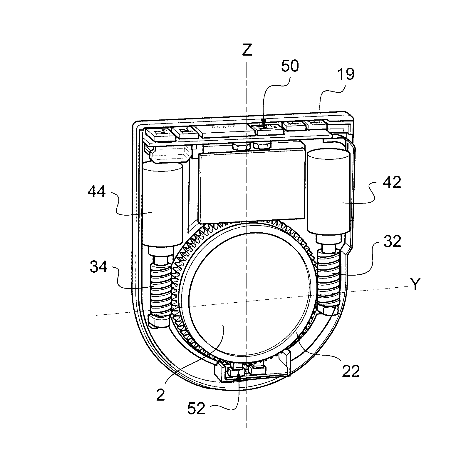
[0053]FIG. 3 shows a cutaway view of the visual compensation system in FIG. 2, from the side of the cylindrical lenses;

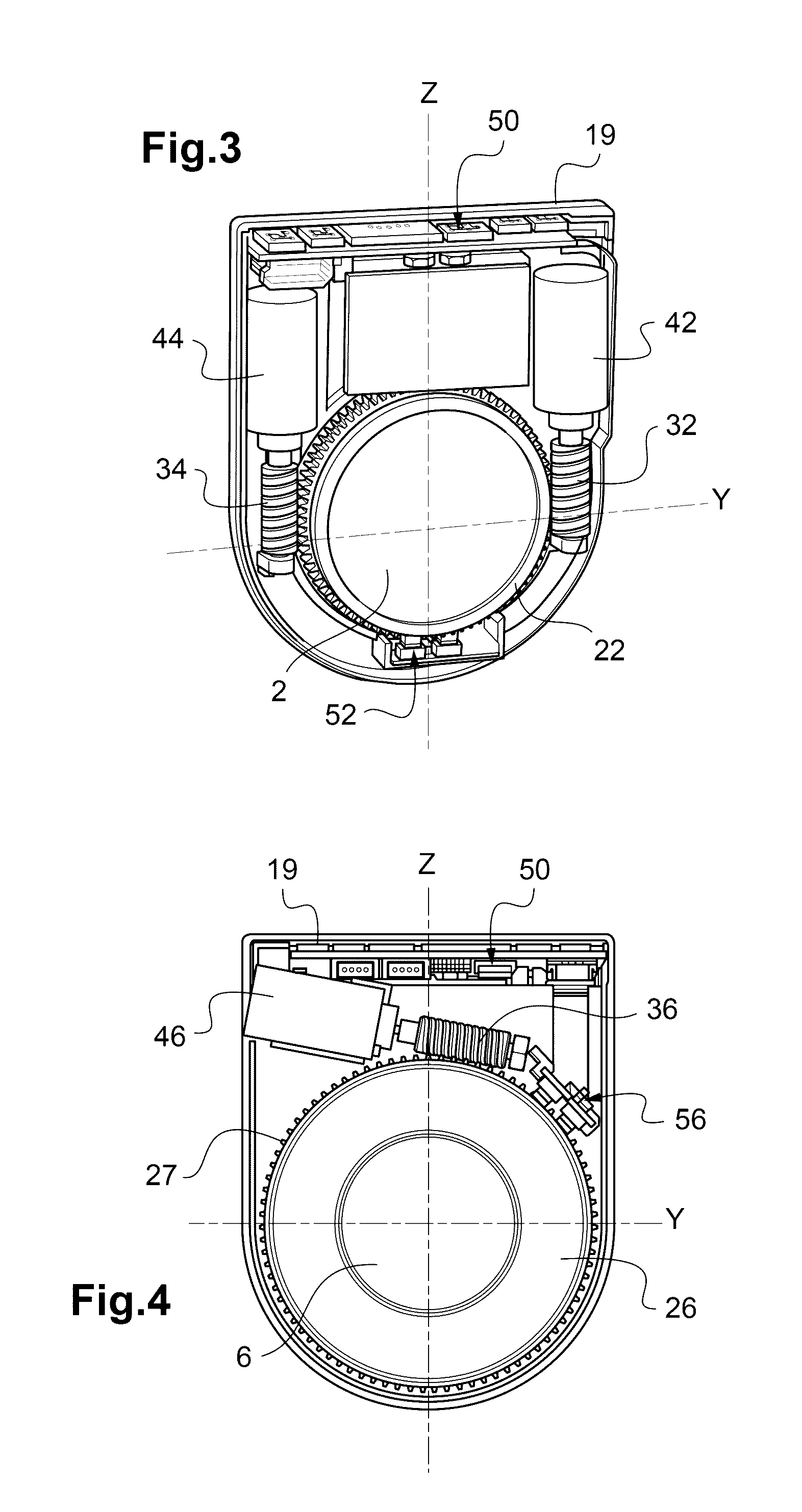
[0054]FIG. 4 shows a cutaway view of the visual compensation system in FIG. 2, from the side of the variable spherical lens;

[0055]FIG. 5 schematically shows an element for controlling the visual compensation system in FIG. 2.

[0056]FIG. 1 schematically shows the main optical elements of an exemplary visual compensation system according to the teachings of the invention.

[0057]These optical elements co...


PUM


Abstract

A visual compensation system (10) enabling observation, with variable optical power correction, along an optical observation axis (X) includes:—a first rotatable optical element (2) centered on the optical axis (X) and having a first cylinder power along the optical axis (X); —a second rotatable optical element (4) centered on the optical axis (X) and having a second cylinder power along the optical axis (X); and—a lens (6) having the optical axis (X) as the axis thereof, and moreover having variable sphere power.

Description

TECHNICAL FIELD TO WHICH THE INVENTION RELATES[0001]The present invention generally relates to the field of optometry.[0002]It more particularly relates to a visual compensation system and to an optometric binocular device comprising such a system.TECHNOLOGICAL BACKGROUND[0003]In the context of the measurement of the visual acuity of a patient, it has already been proposed to simulate the visual compensation to be provided, for example by means of trial frames or a refractor such as a phoropter.[0004]Trial frames are able to receive, in succession, trial lenses providing different corrections, until the suitable correction for the patient is found.[0005]This solution is impractical and requires trial lenses to be stored separately in dedicated boxes. It furthermore involves lens changes, resulting in undesired and non-continuous transitions in corrective power.[0006]In phoropters, trial lenses are placed on a plurality of disks that are rotated manually or using a motorized mechanis...

Claims


Application Information

Patent Timeline
Patent Type & Authority Applications(United States)
IPC IPC(8): A61B3/028G02B3/14G02B7/02A61B3/036
CPCA61B3/0285G02B7/023G02B3/14A61B3/036G02B7/10
Inventor NAUCHE, MICHELBOUTINON, STEPHANE
Owner ESSILOR INT CIE GEN DOPTIQUE
Why Eureka
Try Eureka