Die changer with removable die adapted thereto and die dome as well as method for removing and inserting the removable die

a die changer and die dome technology, applied in the direction of positioning apparatus, metal-working machine components, manufacturing tools, etc., can solve the problems of high maintenance effort, identification codes are susceptible to damage, and require later high maintenance efforts

Active Publication Date: 2016-11-17
BOLLHOFF VERBINDUNGSTECHNIK GMBH
View PDF11 Cites 18 Cited by
  • Summary
  • Abstract
  • Description
  • Claims
  • Application Information

AI Technical Summary

Benefits of technology

The present invention provides a die changer that allows for easy and efficient replacement of removable dies without the need for rotational movements. The die changer includes a die holder with holding openings and an ejection spike for lifting and positioning the removable die. The die holder is designed to accommodate multiple removable dies, allowing for easy selection and replacement. The unique design of the die dome also simplifies the process for arranging, locking, and removing the removable die. The die changer is simple in construction, low in maintenance costs, and easy to use.

Problems solved by technology

Further, a sufficient accuracy at the combined rotational movement and the subsequent linear unlocking or releasing movement of the removable die are necessary which is on the one hand costly in its construction and which requires later high maintenance efforts.
These are not only susceptible due to the complex movement sequences for locking and unlocking the die in the die dome but also due to a contamination which may deposit in the bayonet connection.
Although this identification code, like a bar code, a number code or a two-dimensional code, is detectable by a camera, a scanner or another suitable sensor, these identification codes are susceptible to damaging.
During this movement, the identification codes arranged at the die head are damaged.
This frictional engagement leads also to a damaging of the identification codes so that the identification codes cannot be read or are not identifiable anymore after several changes of the removable die.

Method used


Image

  • Die changer with removable die adapted thereto and die dome as well as method for removing and inserting the removable die
  • Die changer with removable die adapted thereto and die dome as well as method for removing and inserting the removable die
  • Die changer with removable die adapted thereto and die dome as well as method for removing and inserting the removable die

Examples


Embodiment Construction

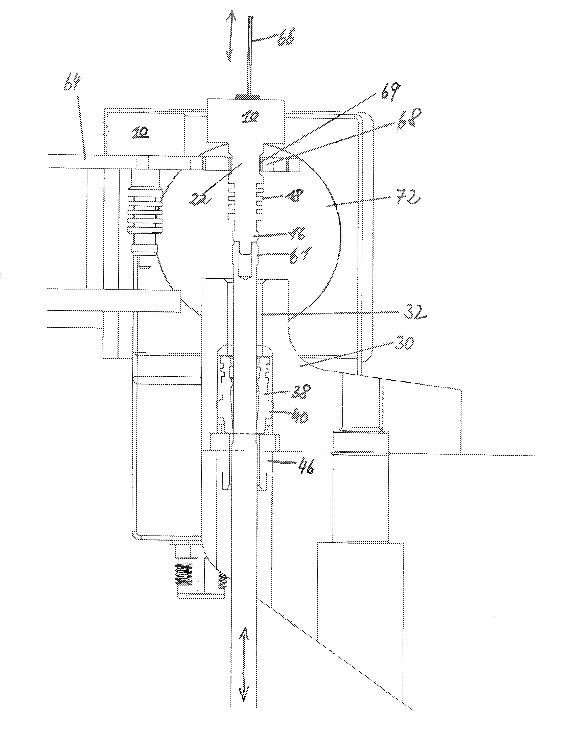
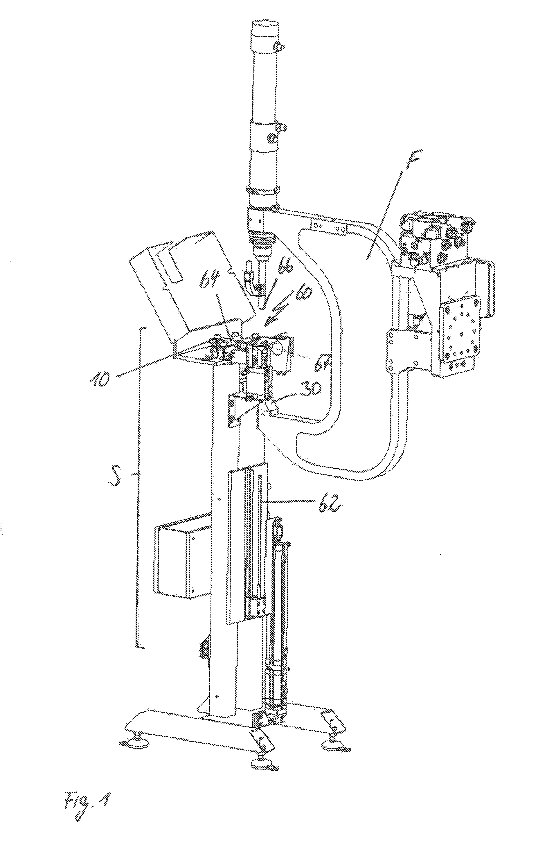
[0049]FIG. 1 shows a perspective overview of a joining device F in combination with a die changer 60. The joining device F is indicated by a C-frame of a setting device. All devices are conceivable as joining devices which use a die, no matter if the joining procedure is performed with or without auxiliary joining part. Such joining devices are for example a setting device for punch rivets, a joining device for clinching or the like. In the following, and for explanation reasons, it is referred to a setting device for punch rivets in combination with a C-frame.

[0050]The setting device is arranged at an open end of the C-frame, wherein a removable die 10 is provided in a die dome 30 at the other open end of the C-frame. The removable die 10 is removably or exchangeably fixed in the die dome 30. This replacement or exchange takes place by means of a die changer 60 preferably comprising an ejection spike 62.

[0051]The ejection spike 62 is linearly, and preferably without rotation, movab...


PUM

PropertyMeasurementUnit
Timeaaaaaaaaaa
Diameteraaaaaaaaaa
Lengthaaaaaaaaaa

Abstract

A removable die of a joining tool comprising a die head having an upper side, a bottom side and a die shaft extending from the bottom side and receivable and lockable in a die dome without rotation. The die shaft comprises: at least one first radial web forming an axial undercut on two sides by which the die shaft is lockable in the die dome by a linear inserting movement, at least one second exposed radial web, the radial length of which is adaptable to a diameter of the die dome to ensure a lateral guiding of the die shaft in the die dome and which is arranged between the die head and the first radial web, and an ejection surface by which the removable die can be moved out of the die dome and which is arranged at the free end of the die shaft opposite to the die head.

Description

1. FIELD OF THE INVENTION[0001]The present invention is related to a die changer for a removable die of a joining device, especially a setting device, the removable die which is adapted thereto as well as a die dome which is adapted to the removable die and a method for removing a removable die of a joining device as well as a method for inserting a removable die into a joining device.2. BACKGROUND OF THE INVENTION[0002]At the manufacturing of products having joining connections, it is meanwhile necessary that different materials, their combinations, different material thicknesses or different auxiliary joining parts have to be processed. This requires always an adapted joining device, as for example a setting device, at the manufacturing of motor vehicles. According to a procedure which is no longer up-to-date, rivet setting devices have been exchanged with each other according to the respective requirements for the joining connection to be produced. These different rivet setting d...

Claims


Application Information

Patent Timeline
IPC IPC(8): B21J15/38B21J15/36
CPCB21J15/36B21J15/38B21J15/025B21J15/10Y10T483/1731Y10T29/49956Y10T29/5377Y10T29/49943Y10T483/10B23Q3/15566B23Q2003/1553B23Q3/15503B23Q3/155B21J15/30
Inventor AHLEMEYER, FABIANPETERS, PETER
Owner BOLLHOFF VERBINDUNGSTECHNIK GMBH
Why Eureka
Try Eureka