System and method for de-icing a heat pump

a heat pump and system technology, applied in the field of system and method for de-icing a heat pump, can solve the problems of heat pump compressor deformation, exterior heat exchanger freezing, and freezing of the exterior heat exchanger fin, so as to reduce the possibility of heat pump compressor degradation, increase the rate of exterior heat exchanger de-icing, and reduce the effect of exterior heat exchanger icing

Inactive Publication Date: 2016-11-17
FORD GLOBAL TECH LLC
View PDF40 Cites 25 Cited by
  • Summary
  • Abstract
  • Description
  • Claims
  • Application Information

AI Technical Summary

Benefits of technology

[0004]By operating the vehicle heat pump in a cooling mode in response to a presence of exterior heat exchanger icing, it may be possible to provide the technical result of increasing a rate of exterior heat exchanger de-icing. Further, operating the heat pump in a cooling mode may reduce the possibility of heat pump compressor degradation. For example, a heat pump may at first be operated in a de-icing mode to reduce exterior heat exchanger icing. However, if the de-icing takes longer than is desired, the heat pump may switch from de-icing mode to a cooling mode to continue exterior heat exchanger de-icing since the heat is rejected to the exterior heat exchanger when the heat pump is operated in a cooling mode. In some examples, passenger comfort may be maintained when the heat pump operates in a cooling mode via activating a positive temperature coefficient (PTC) heater while the exterior heat exchanger is being de-iced in the cooling mode. In other examples, if the vehicle includes an engine, the engine may be activated to maintain passenger comfort while the exterior heat exchanger is being de-iced in the cooling mode.
[0005]The present description may provide several advantages. For example, the approach may improve heat pump efficiency in heating mode by de-icing the exterior heat exchanger. Additionally, the approach may maintain passenger comfort by using an electric coolant heater to reject air to the passenger cabin at a desired temperature during exterior heat exchanger de-icing. Further, the approach may be applicable to both electric and hybrid vehicles.

Problems solved by technology

However, humidity in the ambient air may freeze fins of the exterior heat exchanger as air passes over the heat exchanger fins.
Further, the exterior heat exchanger may freeze during other conditions, such as if snow becomes impacted in the exterior heat exchanger.
Consequently, the heat pump's compressor may be degraded if the heat pump is operated in de-icing mode for an extended period of time.
Additionally, known de-icing methods do not allow the passenger cabin to be heated while the heat pump is operating in de-icing mode.
Further, operating the heat pump in a cooling mode may reduce the possibility of heat pump compressor degradation.

Method used


Image

  • System and method for de-icing a heat pump
  • System and method for de-icing a heat pump
  • System and method for de-icing a heat pump

Examples


Embodiment Construction

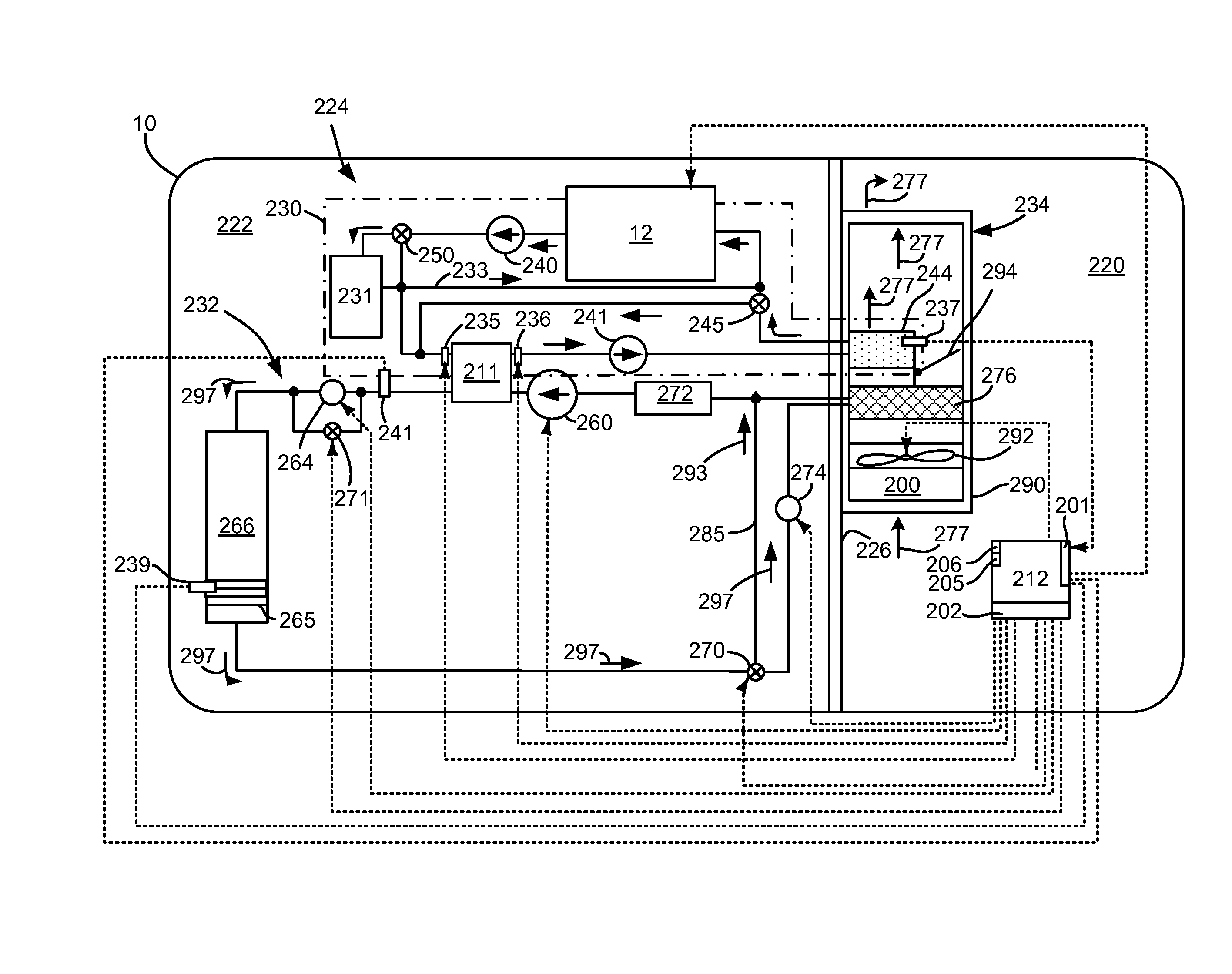
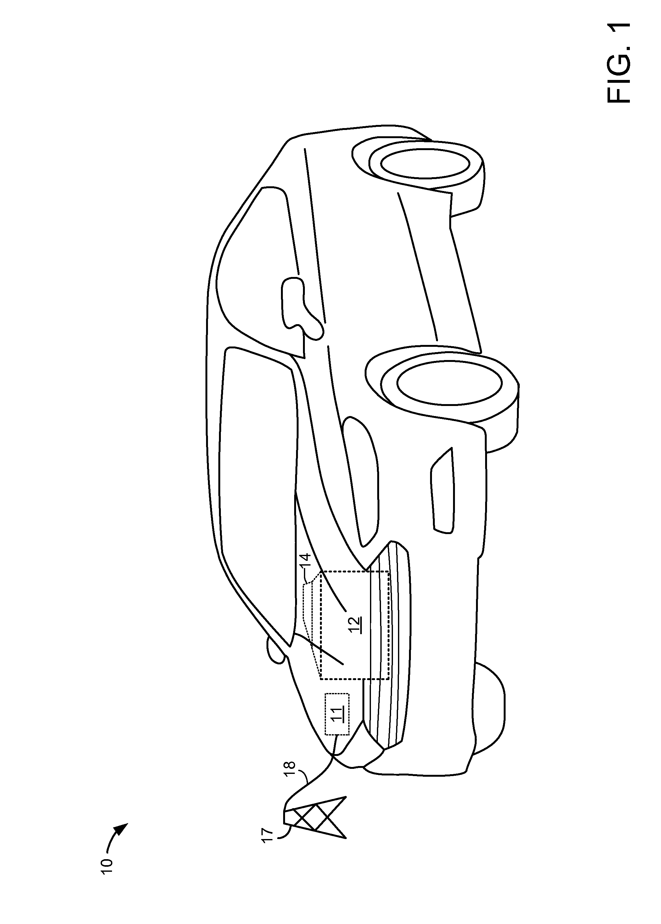
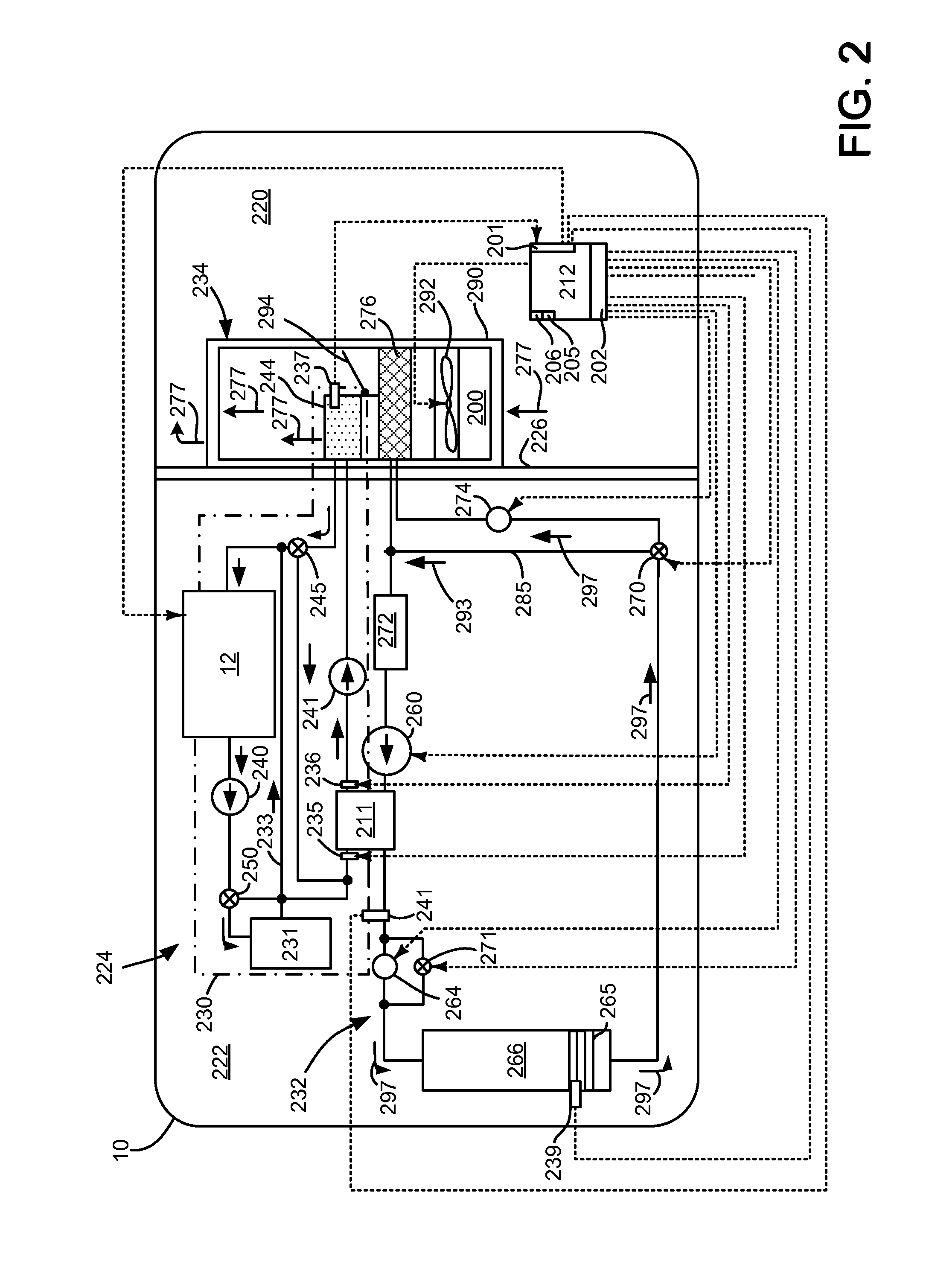
[0014]The present description is related to providing improving vehicle heat pump de-icing. In particular, a vehicle's exterior heat exchanger (e.g., a heat exchanger outside of a passenger cabin) may be de-iced in different modes depending on heat pump operating conditions. The vehicle may be a passenger vehicle as is shown in FIG. 1 or a commercial vehicle (not shown). The vehicle includes a climate control system including a heat pump as is shown in FIG. 2. The climate control system may include an engine that is part of a hybrid powertrain as is shown in FIG. 3. Exterior heat exchanger de-icing may be provided based on the method of FIGS. 4-6. The de-icing process may be performed as shown in the operating sequence of FIG. 7.

[0015]Referring to FIG. 1, a vehicle 10 including an engine 12, an electrical machine 14, and an electrical energy storage device 11 is shown. In one example, the vehicle may be propelled solely via the engine 12, solely via the electrical machine 14, or by ...


PUM


Abstract

Methods and system for providing de-icing a heat pump heat exchanger and heating a vehicle passenger cabin are presented. In one example, a heat pump that experiences icing of exterior heat exchanger fins may be operated in a cooling mode where a passenger cabin heat exchanger operates as an evaporator to improve de-icing of the exterior heat exchanger fins.

Description

FIELD[0001]The present description relates to a system and methods for improving de-icing of an exterior heat exchanger in a vehicle heat pump. The system and methods may be particularly useful for vehicles that operate at lower ambient temperatures and supply passenger cabin heating.BACKGROUND AND SUMMARY[0002]A hybrid or electric vehicle may include a heat pump for heating and cooling a passenger cabin responsive to a desired passenger cabin temperature. During some conditions where ambient air temperature is low and cabin heating is requested, an exterior heat exchanger may be operated as an evaporator to extract heat from ambient air to heat the passenger cabin. However, humidity in the ambient air may freeze fins of the exterior heat exchanger as air passes over the heat exchanger fins. Further, the exterior heat exchanger may freeze during other conditions, such as if snow becomes impacted in the exterior heat exchanger. If the exterior heat exchanger fins remain in an iced st...

Claims


Application Information

Patent Timeline
Patent Type & Authority Applications(United States)
IPC IPC(8): B60H1/00B60H1/32
CPCB60H1/00785B60H1/3213B60H1/00907B60H1/321B60H1/00921B60H2001/00928B60H2001/00961F25B5/04F25B6/04F25B47/022F25B49/02F25B2339/047F25B2400/0409F25B2400/0411F25B2600/2513F25B41/39B60H1/00885B60H1/00899B60H1/034F25B2700/11
Inventor BLATCHLEY, TIMOTHY NOAHRAGAZZI, FRANCO
Owner FORD GLOBAL TECH LLC
Why Eureka
Try Eureka