
Control device for an internal combustion engine

a control device and internal combustion engine technology, applied in the direction of electric control, engine starters, machines/engines, etc., can solve the problems of insufficient inertia after ignition, engine failure to re-start, engine failure to achieve sufficient inertia, etc., to achieve accurate angular velocity

Active Publication Date: 2016-11-17
TOYOTA JIDOSHA KK
View PDF6 Cites 0 Cited by
  • Summary
  • Abstract
  • Description
  • Claims
  • Application Information

AI Technical Summary

Benefits of technology

The patent describes a device that can accurately predict the angle of a crank in an engine. This information helps the device to start the engine up again after it has been stopped. The device uses a more accurate measurement of speed to make this prediction, which ensures that the engine can be started up quickly and reliably.

Problems solved by technology

However, the compression in the expansion stroke cylinder is not necessarily increased sufficiently just because the rotational direction of the engine is inverted to the reversed rotational direction.
Even though a fuel injection and an ignition are performed when the compression in the expansion stroke cylinder is not sufficiently high, sufficient inertia may not be obtained after ignition and an engine may not be re-started.
Therefore, even though the compression of the expansion stroke cylinder is sufficiently high at the time when the re-start condition is satisfied, compression may be decreased when fuel is actually ignited, and inertia sufficient to re-start the engine may not be obtained after ignition.
In such a case, an engine cannot be certainly re-started by the ignition start-up.

Method used


Image

  • Control device for an internal combustion engine
  • Control device for an internal combustion engine
  • Control device for an internal combustion engine

Examples


Embodiment Construction

[0048]Hereafter, a “control device for an internal combustion engine” according to an embodiment of the present invention (hereafter, may be referred to as the “present device”) will be explained.

(Configuration)

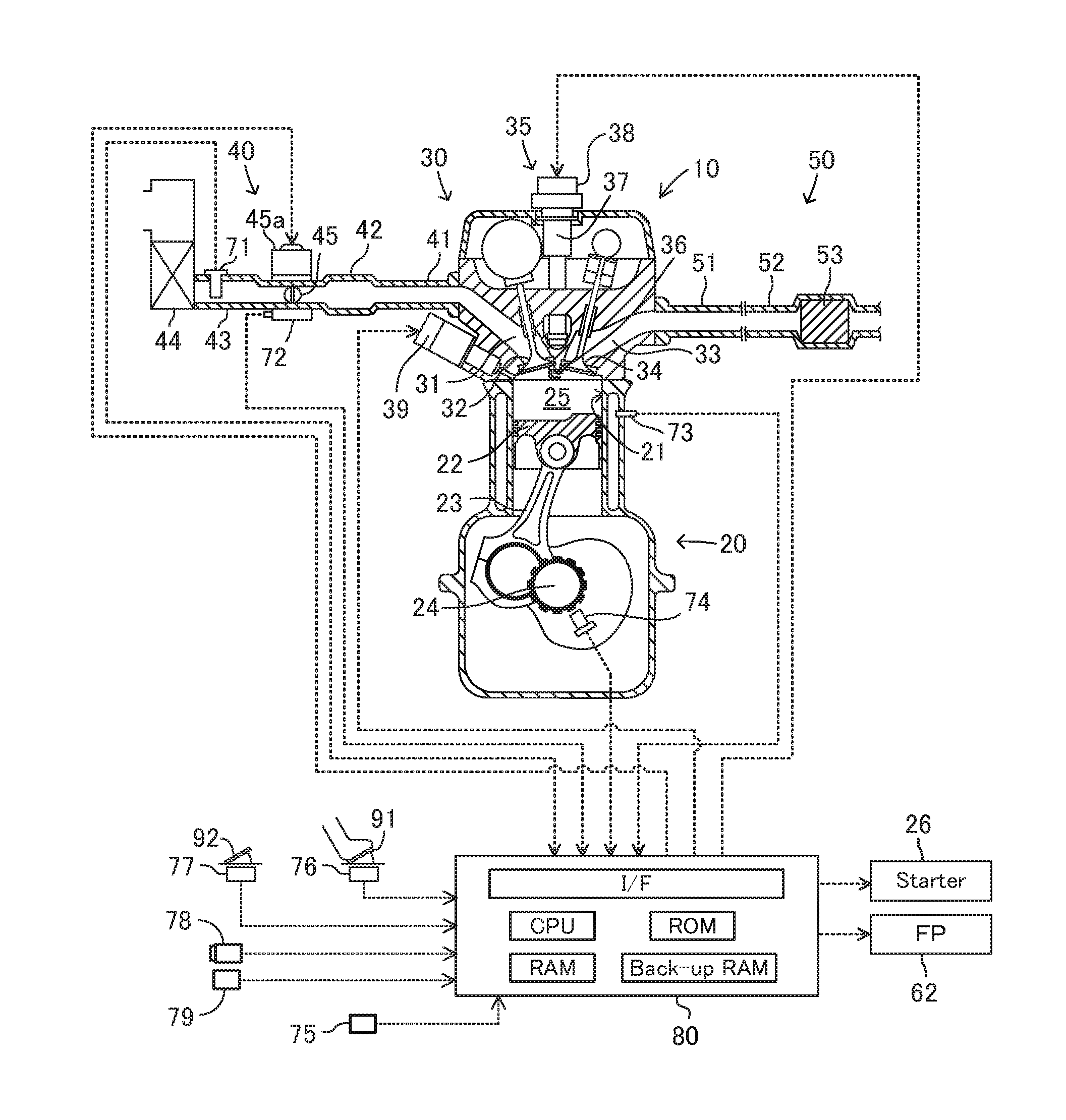
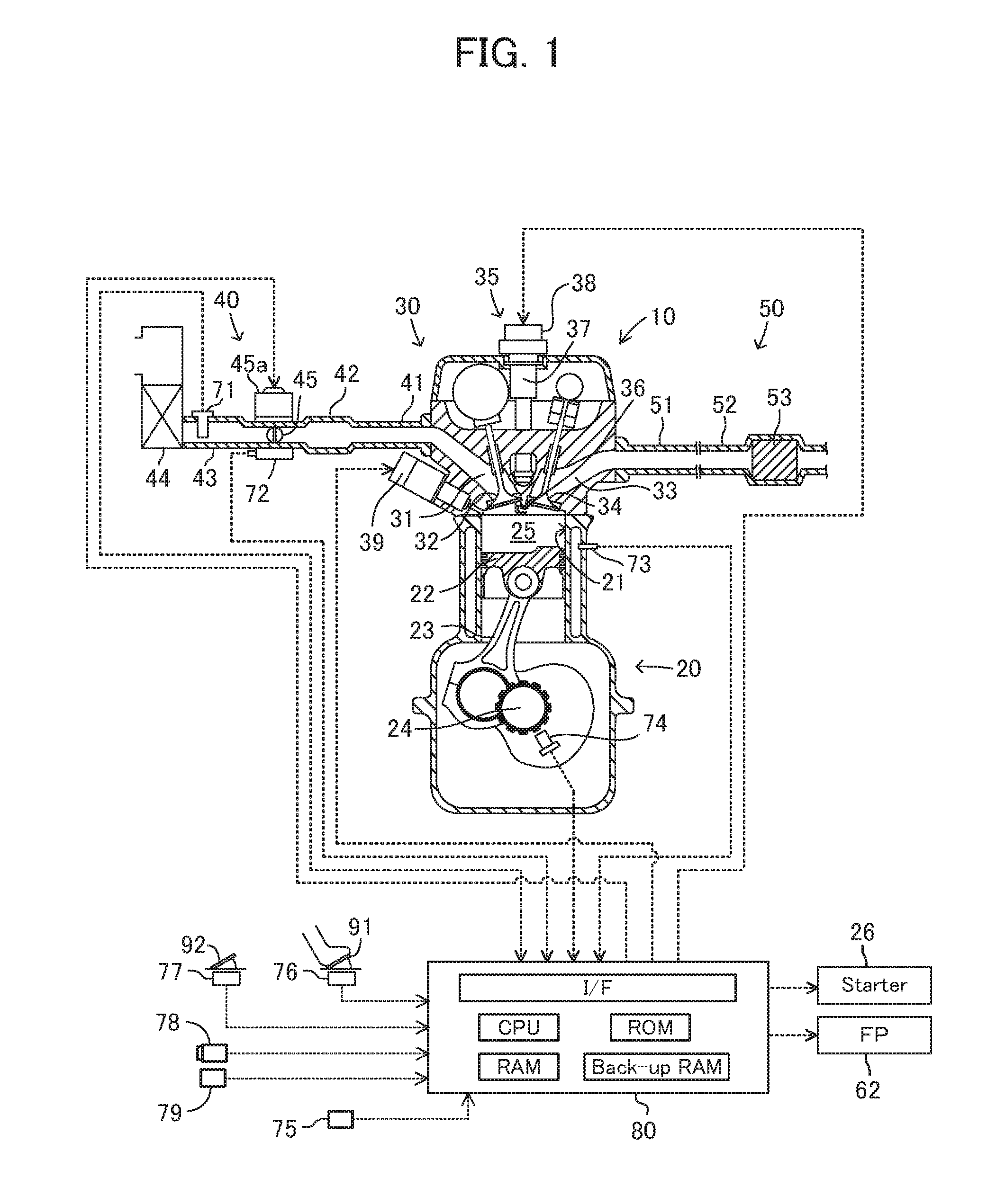
[0049]The present device is applied to an internal combustion engine (engine) 10 showed in FIG. 1. The engine 10 is a multi-cylinder (in this example, in-line four-cylinder) four-stroke piston-reciprocating cylinder-injection (direct injection), a spark-ignition gasoline-fuel engine.

[0050]The engine 10 comprises a cylinder block part 20 including a cylinder block, a cylinder block lower case, oil pan, etc., a cylinder head part 30 fixed on the cylinder block part 20, an intake system 40 for supplying air to the cylinder block part 20, and an exhaust system 50 for emitting exhaust gas from the cylinder block part 20 to the outside.

[0051]The cylinder block part 20 comprises a cylinder 21, a piston 22, a connecting rod 23, and a crankshaft 24. The piston 22 reciprocates inside t...


PUM


Abstract

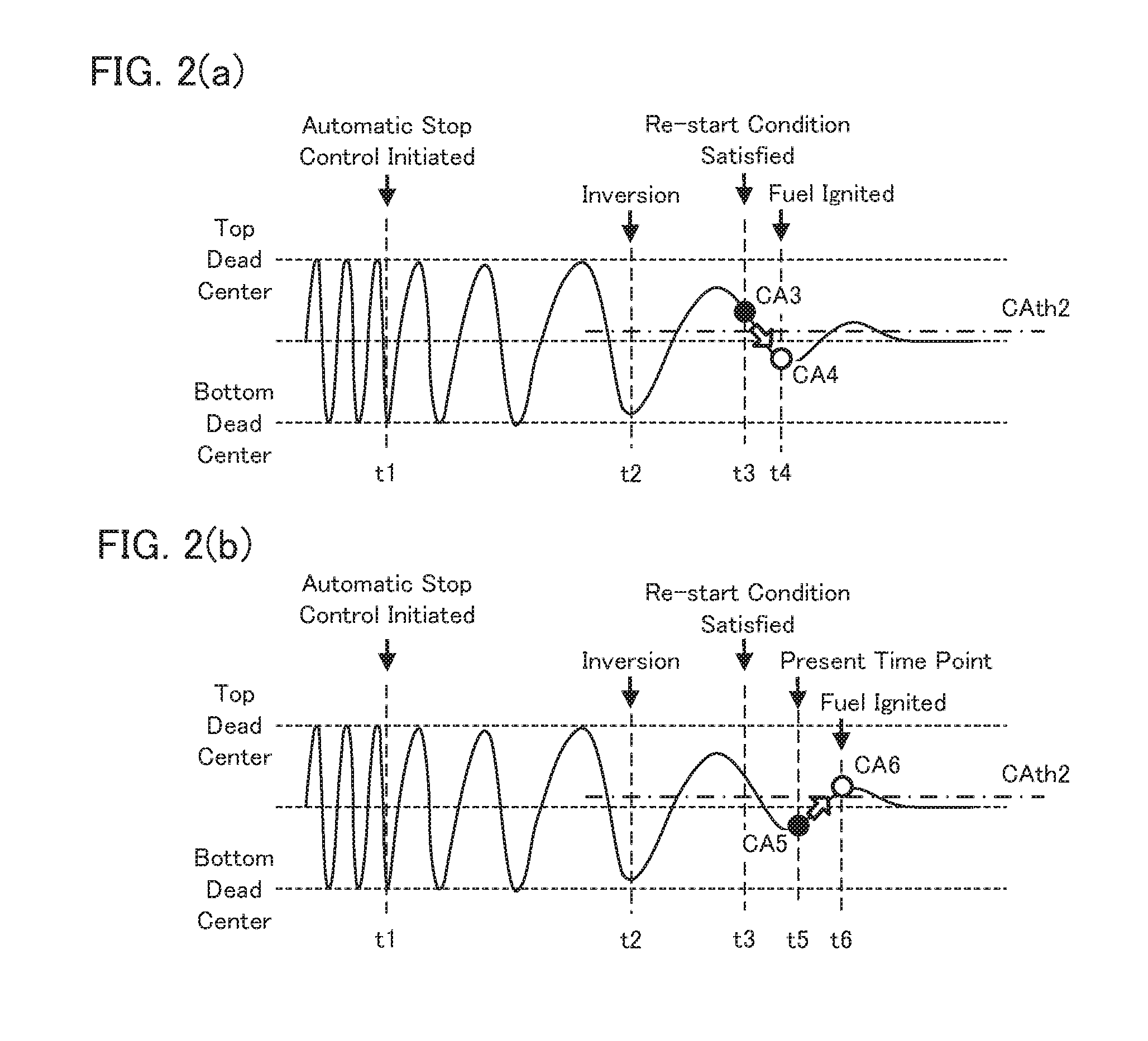
A control device according to the present invention performs an automatic stop control in which an injection of fuel from a fuel injection valve is stopped and a rotation of an engine is stopped when an automatic stop condition is satisfied. Furthermore, the control device controls an injection operation of fuel and an ignition operation to the fuel in consideration of compression when the fuel is actually ignited in an expansion stroke cylinder, when a re-start demand occurs after an initiation of the automatic stop control and the engine is to be re-started by an ignition start-up. Specifically, the control device predicts a crank angle at an actual ignition time point in a case where processing for performing the ignition start-up at the present time whenever a predetermined time period has passed. Then, the control device initiates the ignition start-up when the crank angle falls within a predetermined range in which a sufficient compression can be attained. Thereby, the engine is more certainly re-started by the ignition start-up.

Description

CROSS-REFERENCE TO RELATED APPLICATION[0001]The present application claims priority to Japanese Patent Application No. 2015-096224 filed on May 11, 2015, which is incorporated herein by reference in its entirety.TECHNICAL FIELD[0002]The present invention relates to a control device which has a function to automatically stop and re-start an internal combustion engine (hereafter may be referred to as an “engine”).BACKGROUND ART[0003]Conventionally, a control device that performs an automatic stop control in which operation (rotation) of an engine is automatically stopped when a predetermined automatic stop condition is satisfied for the purpose of improvement of fuel consumption of a vehicle carrying an engine and reduction of a quantity of exhaust gas discharged from the vehicle has been known.[0004]Such a control device will re-start an engine automatically, when a demand for re-start of an engine occurs in a case where an accelerator pedal operation is made or in a case where a bra...

Claims


Application Information

Patent Timeline
Patent Type & Authority Applications(United States)
IPC IPC(8): B60W30/18F02D17/04F02D41/04B60W10/06
CPCB60W30/18018B60W10/06B60W2520/04F02D41/042B60W2510/0685F02D17/04F02D41/062F02D41/30F02N11/0844F02N99/004F02N99/006F02N2019/007F02N2200/022F02N2250/04F02N2300/2002Y02T10/40F02N2200/021F02N11/0825F02N2019/008
Inventor SUZUKI, YUSUKEKOJIMA, SUSUMU
Owner TOYOTA JIDOSHA KK
Learn More