Laminated structure provided with movable portion

a technology of laminated structure and movable portion, which is applied in the direction of acceleration measurement in multiple dimensions, turn-sensitive devices, instruments, etc., can solve the problems of reducing the number of movable structure able to be manufactured from a single substrate, reducing the number of structures, and increasing the number of structures. , the effect of reducing the manufacturing cost per structur

Active Publication Date: 2014-04-29
TOYOTA CENT RES & DEV LAB INC
View PDF36 Cites 0 Cited by
  • Summary
  • Abstract
  • Description
  • Claims
  • Application Information

AI Technical Summary

Benefits of technology

[0013](3) increase the number of structures that can be manufactured from a single substrate and decrease manufacturing cost per structure by employing a nested structure for the first movable portion and the second movable portion.
[0019](3) increasing the number of structures that can be manufactured from a single substrate and decreasing manufacturing cost per structure by employing a nested structure for the first movable portion (the inner movable portion) and the second movable portion (the outer movable portion) since the inner movable portion is housed within the outer movable portion when viewed from the z-axis direction.
[0027]According to the structure described above, a relationship is obtained in which the x relaying portion can be reciprocatory oscillated in the x-axis direction by an oscillating portion, and the outer movable portion and the inner movable portion are reciprocatory oscillated in the x-axis direction by following therewith. The inner movable portion is displaced in the z-axis direction by Coriolis force if angular velocity about the y-axis is applied. The inner movable portion is displaced in the z-axis direction while reciprocatory oscillating in the x-axis direction. Although the z relaying portion is displaced in the z-axis direction by following z-axis directional displacement of the inner movable portion, it is not displaced in the x-axis direction. Namely, the z relaying portion is only displaced in the z-axis direction due to Coriolis force in the z-axis direction. Since the z displacement detection unit detects an amount of z-axis directional displacement of the z relaying portion that is displaced only in the z-axis direction, it accurately detects angular velocity about the y-axis by accurately detecting Coriolis force in the z-axis direction. A similar occurrence is also obtained when angular velocity about the z-axis is applied. The outer movable portion is displaced in the y-axis direction by Coriolis force if angular velocity about the z-axis is applied. The outer movable portion is displaced in the y-axis direction while reciprocatory oscillating in the x-axis direction. Although the y relaying portion is displaced in the y-axis direction by following y-axis directional displacement of the outer movable portion, it is not displaced in the x-axis direction. Namely, the y relaying portion is only displaced in the y-axis direction due to Coriolis force in the y-axis direction. Since the y displacement detection unit detects an amount of y-axis directional displacement of the y relaying portion that is only displaced in the y-axis direction, angular velocity about the z-axis can accurately be detected by accurately detecting Coriolis force in the y-axis direction. Angular velocities about the y-axis and the z-axis can be detected by the structure described above.
[0034](3) increasing the number of structures that can be manufactured from a single substrate and decreasing manufacturing cost per structure by employing a nested structure for the first movable portion (the inner movable portion) and the second movable portion (the outer movable portion).
[0041]According to the structure described above, a relationship is obtained in which the x relaying portion can be reciprocatory oscillated in the x-axis direction by the oscillating portion, and the outer movable portion and the inner movable portion can be reciprocatory oscillated in the x-axis direction by following therewith. The inner movable portion is displaced in the z-axis direction by Coriolis force if angular velocity about the y-axis is applied. The inner movable portion is displaced in the z-axis direction while reciprocatory oscillating in the x-axis direction. Although the z relaying portion is displaced in the z-axis direction by following z-axis directional displacement of the inner movable portion, it is not displaced in the x-axis direction. Namely, the z relaying portion is only displaced in the z-axis direction due to Coriolis force in the z-axis direction. Since the z displacement detection unit detects an amount of z-axis directional displacement of the z relaying portion that is only displaced in the z-axis direction, Coriolis force in the z-axis direction is accurately detected, and angular velocity about the y-axis is accurately detected. A similar occurrence is also obtained when angular velocity about the z-axis is applied. The outer movable portion is displaced in the y-axis direction by Coriolis force if angular velocity about the z-axis is applied. The outer movable portion is displaced in the y-axis direction while reciprocatory oscillating in the x-axis direction. Although the y relaying portion is displaced in the y-axis direction by following y-axis directional displacement of the outer movable portion, it is not displaced in the x-axis direction. Namely, the y relaying portion is only displaced in the y-axis direction due to Coriolis force in the y-axis direction. Since the y displacement detection unit detects an amount of y-axis directional displacement of the y relaying portion that is only displaced in the y-axis direction, Coriolis force in the y-axis direction is accurately detected, and angular velocity about the z-axis is accurately detected. According to the structure described above, angular velocities can be detected about the y-axis and the z-axis.

Problems solved by technology

However, the prior art is limited to a structure in which all of the two or more movable portions are able to move within a plane parallel to a substrate surface, and is unable to realize a structure provided with a portion that is able to move in a direction perpendicular to the substrate surface with a laminated structure.
However, a biaxial angular velocity sensor or a triaxial acceleration sensor cannot be realized that require both a portion that is able to move in a direction perpendicular to the substrate surface and a portion that is able to move in a plane parallel to the substrate surface.
As a result, the number of movable structures able to be manufactured from a single substrate would end up decreasing, and manufacturing cost per movable structure would end up increasing.

Method used


Image

  • Laminated structure provided with movable portion
  • Laminated structure provided with movable portion
  • Laminated structure provided with movable portion

Examples


embodiment 1

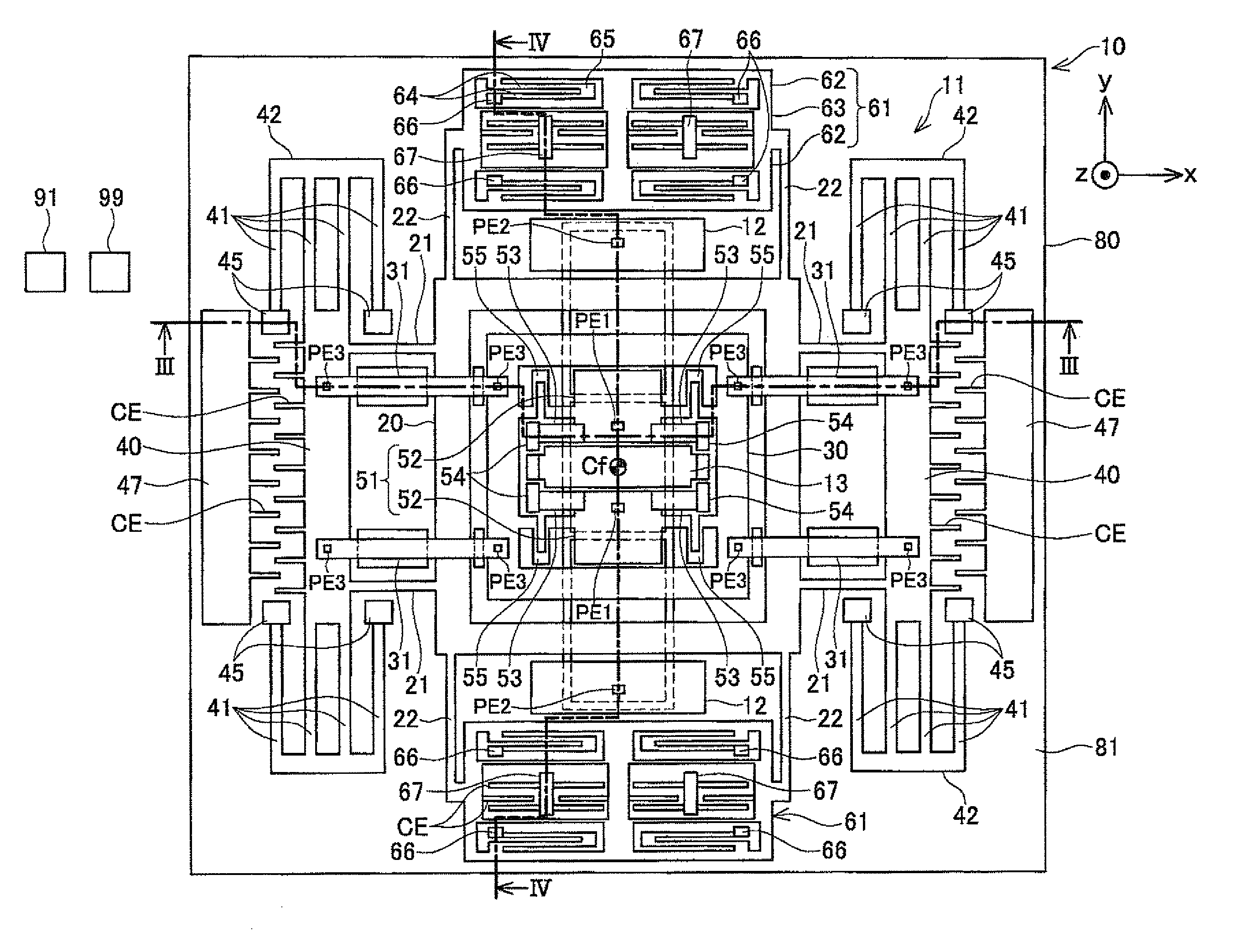
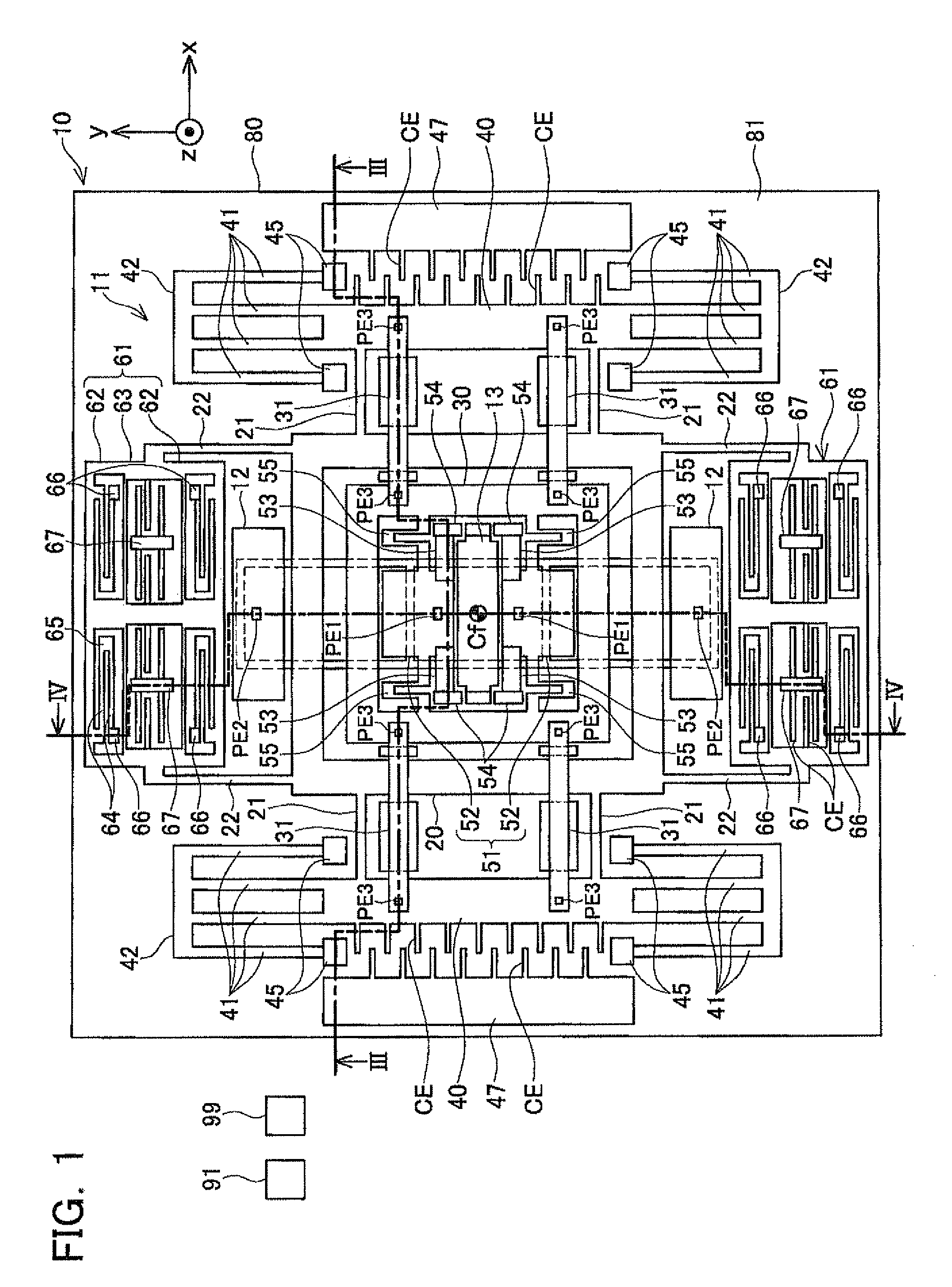
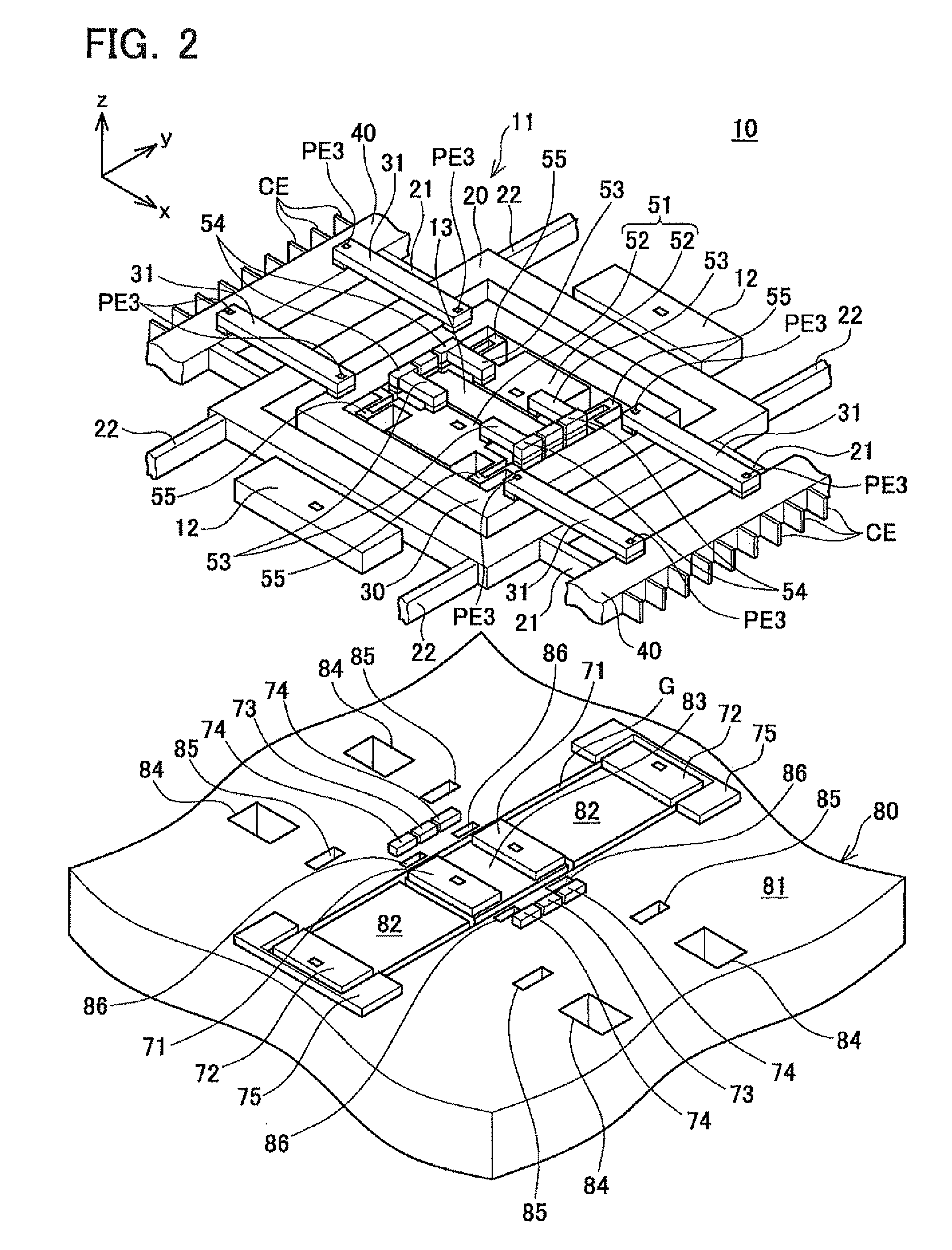
[0070]The following provides an explanation of Embodiment 1, in which a laminated structure according to the present invention is applied to a biaxial angular velocity sensor, with reference to FIGS. 1 to 4. A laminated structure 10 of the present embodiment is manufactured by etching a prescribed range of each layer of a double SOI substrate. The double SOI substrate used in the present embodiment has a five-layer structure, and is obtained by laminating in order starting from the top a silicon layer having a thickness of 5 μm (to be referred to as a first silicon layer), a silicon oxide layer having a thickness of 3 μm (to be referred to as a first oxide film), a silicon layer having a thickness of 15 μm (to be referred to as a second silicon layer), a silicon oxide layer having a thickness of 3 μm (to be referred to as a second oxide film), and a silicon layer having a thickness of 300 μm (to be referred to as a third silicon layer or substrate). The first silicon layer and the s...

embodiment 2

[0100]The following provides an explanation of an Embodiment 2 in which the laminated structure according to the present invention is applied to a triaxial acceleration sensor with reference to FIG. 5. As shown in FIG. 5, a laminated structure 100 of the present embodiment is obtained by etching a prescribed range of each layer of a double SOI substrate in the same manner as the previously described Embodiment 1. The laminated structure 100 of the present embodiment is provided with a movable structure 101 that differs from Embodiment 1. In the movable structure 101 of the present embodiment, together with being provided with two x relaying portions 110 shown in FIG. 5 instead of the two x relaying portions 40 of Embodiment 1, two x direction stationary electrodes 115 are provided instead of the excitation electrodes 47 of Embodiment 1. The laminated structure 100 is electrically connected to an x displacement output unit 103, the y displacement output unit 99 and the z displacement...

embodiment 3

[0105]The following provides an explanation of an Embodiment 3 in which the laminated structure according to the present invention is applied to a biaxial angular velocity sensor with reference to FIGS. 6 and 7. As shown in FIG. 6, a laminated structure 120 of the present embodiment is obtained by etching a specified range of each layer of a double SOI substrate in the same manner as each of the previously described embodiments. A biaxial angular velocity sensor is composed of this laminated structure 120, the y displacement output unit 99 and the z displacement output unit 91. The laminated structure 120 of the present embodiment is provided with a movable structure 121 that differs from Embodiment 1. The movable structure 121 is provided with four y-z springs 123 instead of the four first z springs 31 of Embodiment 1. As shown in FIG. 7, the openings 84 and 85 of Embodiment 1 are not formed in an outer substrate 126 of a substrate 125 since the first z springs 31 are not present i...


PUM


Abstract

A structure having a first movable portion displaced perpendicular to a substrate surface and a second movable portion displaced parallel to the substrate surface is realized by a laminated structure employing a nested structure for the first portion and the second portion. The laminated structure is provided with inner and outer movable portions. A y spring is connected to the outer portion, and the outer portion is supported in a y-axis direction by the y spring at a height apart from an outer substrate. A z spring is connected to the inner portion, and the inner portion is supported in a z-axis direction by the z spring at a height apart from the outer substrate. The outer portion and the z spring are at different heights from the substrate, and the z spring overpasses across the outer portion at a height apart from the outer movable portion.

Description

CROSS-REFERENCE TO RELATED APPLICATION[0001]This application claims priority to Japanese Patent Application No. 2010-070077 filed on Mar. 25, 2010, the contents of which are hereby incorporated by reference into the present application.TECHNICAL FIELD[0002]The present application relates to a laminated structure provided with movable portions. More particularly, the present application relates to a laminated structure provided with a first movable portion that is able to move in a direction perpendicular to a substrate surface and a second movable portion that is able to move in a direction parallel to a substrate surface. The laminated structure as referred to here indicates a laminated structure in which each constituent portion extends parallel to a substrate surface and constituent portions are integrated over a range in which they make contact in a vertical direction. Such a laminated structure is manufactured by executing etching in a prescribed pattern for each layer of a lam...

Claims


Application Information

Patent Timeline
Patent Type & Authority Patents(United States)
IPC IPC(8): G01C19/56G01C19/5762G01P15/125
CPCG01P15/125G01C19/574G01P15/18G01P2015/082
Inventor AKASHI, TERUHISANONOMURA, YUTAKAFUJIYOSHI, MOTOHIROFUNABASHI, HIROFUMIHATA, YOSHIYUKIOMURA, YOSHITERU
Owner TOYOTA CENT RES & DEV LAB INC
Why Eureka
Try Eureka