Zoom lens

a zoom lens and zoom technology, applied in the field of zoom lenses, can solve the problems of poor sensitivity, increased manufacturing cost, and larger lens size, and achieve the effects of large aperture, high resolution, and large apertur

Inactive Publication Date: 2016-11-17
CALIN TECH
View PDF0 Cites 29 Cited by
  • Summary
  • Abstract
  • Description
  • Claims
  • Application Information

AI Technical Summary

Benefits of technology

[0008]In view of the above, the primary objective of the present invention is to provide a zoom lens, which has the characteristic of a large aperture from a wide-angle end to a telephoto end thereof, and can be compatible with a large optical image sensor of, for example, ½ inches. In addition, the size of the zoom lens can be still compact, and the total length is comparable to that of a conventional lens. Furthermore, the zoom lens provided in the present invention can correct aberration from visible light to infrared light, provide high resolution and the effect of large aperture, and has the advantage of ease of manufacture and assembly.
[0010]With the aforementioned design, the size of the zoom lens can be still compact, while the total lens can be comparable to that of a conventional zoom lens. Furthermore, the zoom lens provided in the present invention is compatible with a large image sensor of, for example, ½ inches. In addition, the aberration from visible light to infrared light can be corrected by the zoom lens, which also provides high resolution and the effect of large aperture, and has the advantage of ease of manufacture and assembly.

Problems solved by technology

However, an image sensor would need a larger image format when pixels are increase to exceed 5 million, for smaller single pixel size causes poor sensitivity.
The problem is, with an image sensor which has a larger image format, not only the size of lens becomes larger, but also the manufacturing cost rises.
It can be seen from the above description that the design of conventional zoom lenses is not perfect, for it is insufficient to satisfy the market of high-end applications which demands high resolution.

Method used


Image

  • Zoom lens
  • Zoom lens
  • Zoom lens

Examples


Embodiment Construction

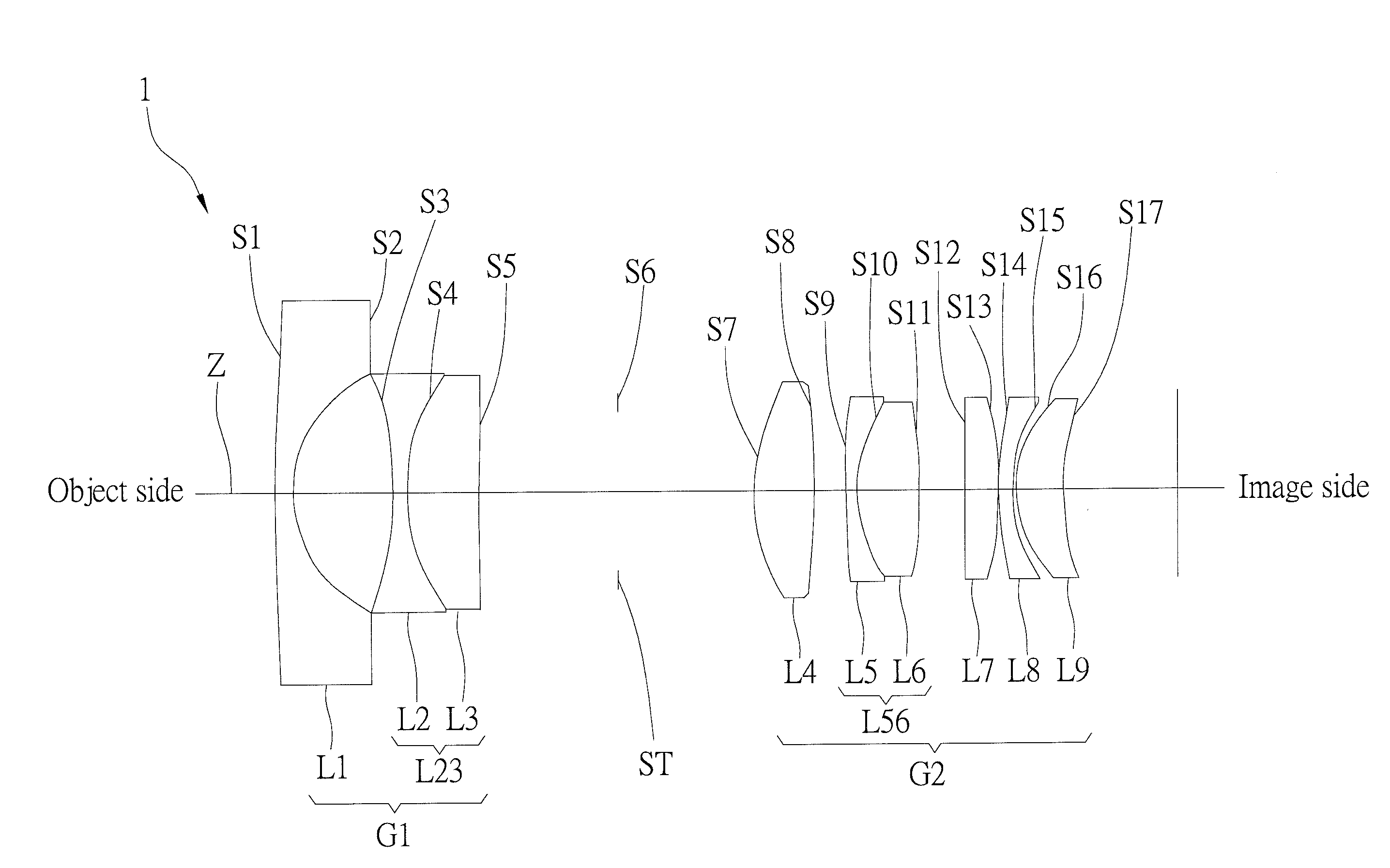
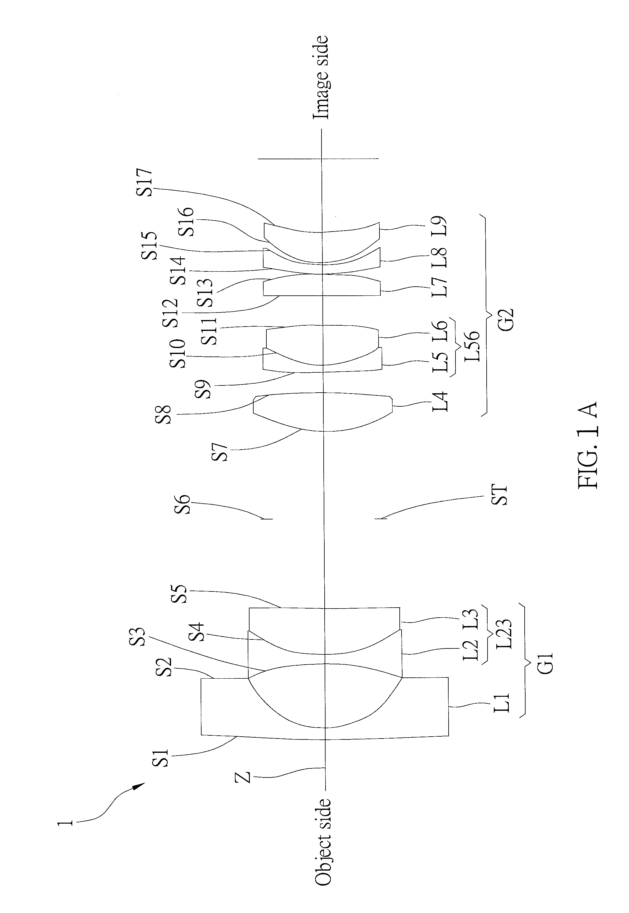
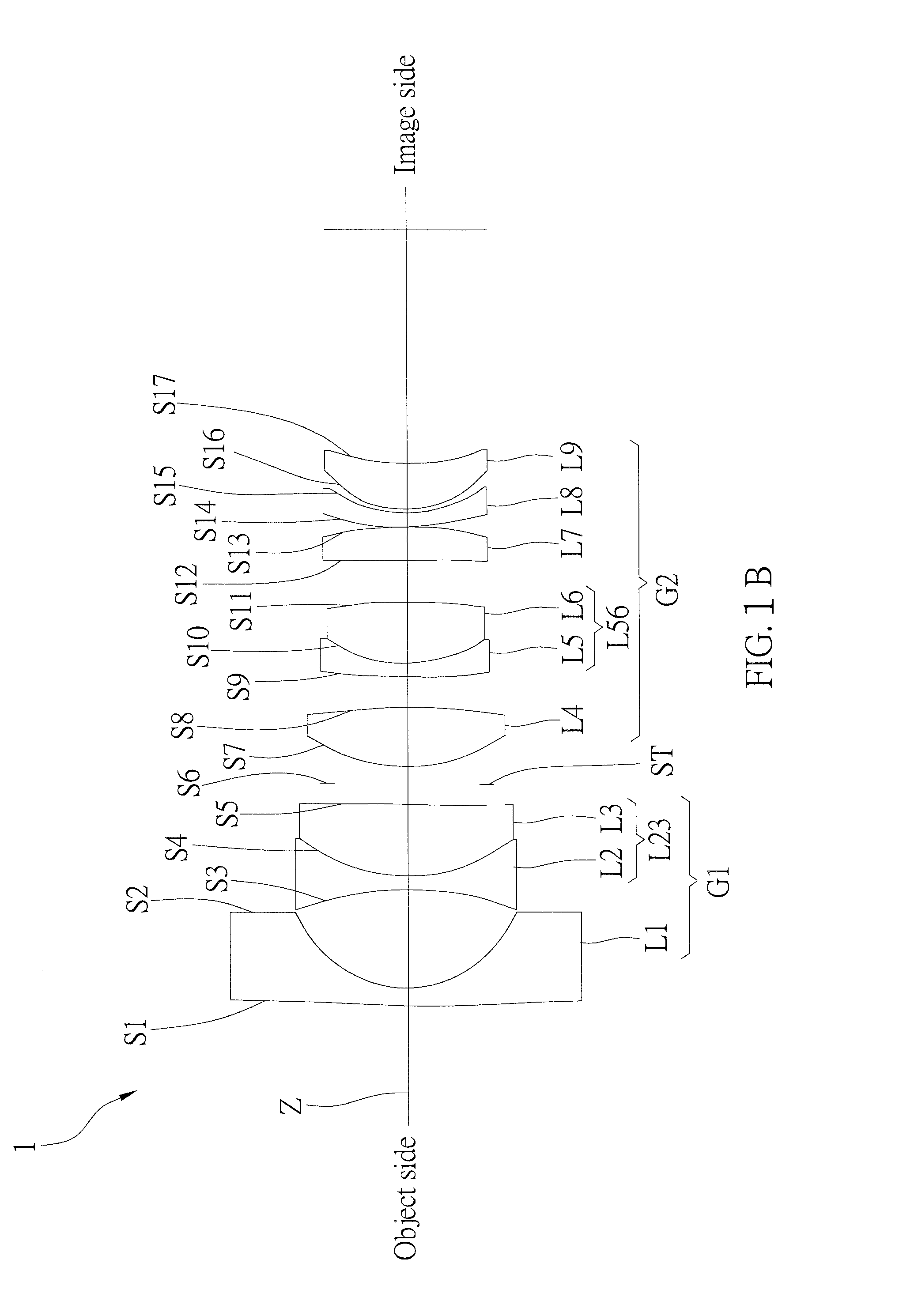
[0053]Zoom lenses 1-5 of the first to the fifth preferred embodiments of the present invention at a wide-angle end and at a telephoto end thereof are respectively shown in FIGS. 1A and 1B, FIGS. 3A and 3B, FIGS. 5A and 5B, FIGS. 7A and 7B, and FIGS. 9A and 9B.

[0054]Each of the zoom lenses 1-5 includes, in order from an object side to an image side along an optical axis Z, a first lens group G1, an aperture ST, and a second lens group G2. In addition, according to different requirements, the zoom lenses 1-5 can further include an optical filter provided at the aperture or between the second lens group G2 and the image side to filter out unwanted optical noise to enhance the optical performance Of course, the position of the optical filter can be changed to meet different design requirements, and is not limited by the above description.

[0055]The first lens group G1 has negative refractive power, and is composed of a first lens L1, a second lens L2, and a third lens L3 which are arrang...


PUM


Abstract

A zoom lens includes, in order from an object side to an image side, a first lens group, an aperture, and a second lens group. The first lens group has negative refractive power, and is composed of a negative first lens, a negative second lens, and a positive third lens. The third lens and the second lens are adhered together to form a negative doublet. The second lens group has positive refractive power, and is composed of a positive fourth lens, a negative fifth lens, a positive sixth lens, a positive seventh lens, a negative eighth lens, and a positive ninth lens. The sixth lens and the fifth lens are adhered together to form a negative doublet. In addition, the first lens group can be moved between the object side and the aperture, while the second lens group can be moved between the aperture and the image side.

Description

BACKGROUND OF THE INVENTION[0001]1. Technical Field[0002]The present invention relates generally to optical lens, and more particularly to a zoom lens.[0003]2. Description of Related Art[0004]With the recent advancement in semiconductor technology, optical devices such as surveillance cameras are possible to provide images of higher quality, and hence the lenses used in such devices are required to provide higher resolution for the increasing demand in image sensors including more pixels. More specifically, it would be preferable to have a lens which has a wide viewing angle at a short focus end. In addition, lower manufacturing cost and more compact size are always welcomed by manufactures and end-users too.[0005]When in the daytime, the lens of the aforementioned optical devices uses visible light to capture images; when in night, near infrared light is used instead. In order to ensure that captured images have sufficient brightness even in a dim environment, the aforementioned op...

Claims


Application Information

Patent Timeline
Patent Type & Authority Applications(United States)
IPC IPC(8): G02B15/177G02B13/00
CPCG02B9/00G02B15/177G02B13/0045G02B13/18G02B13/009G02B15/14G02B9/64G02B13/008G02B15/1425
Inventor LEE, MING-LINTSENG, CHIEN-HSIUNG
Owner CALIN TECH
Why Eureka
Try Eureka