Unlock instant, AI-driven research and patent intelligence for your innovation.

Encoding device, decoding device, encoding method, decoding method, and non-transitory computer-readable recording medium

a computer-readable recording medium and encoding device technology, applied in the field of encoding device, decoding device, encoding method, decoding method, etc., can solve the problems of reducing subjective quality, generating noise that sounds like a ringing bell, and contradicting the efficient use of radio waves or frequency bands, so as to reduce the overall bit rate and improve the quality

Active Publication Date: 2016-11-17
FRAUNHOFER GESELLSCHAFT ZUR FOERDERUNG DER ANGEWANDTEN FORSCHUNG EV
View PDF23 Cites 0 Cited by
  • Summary
  • Abstract
  • Description
  • Claims
  • Application Information

AI Technical Summary

Benefits of technology

This patent describes a device that can improve the quality of voice signals by separating out the "tonal" and "non-tonal" components of the signal and using them separately for encoding. This results in a higher quality signal that requires less data during storage and transmission. The device also describes a decoder that can restore the original voice signal quality by using the same encoding and decoding techniques. Overall, this technology allows for better quality voice signals to be recorded, stored, and transmitted using less data.

Problems solved by technology

However, this approach contradicts efficient use of radio waves or frequency bands.
Thus, noise that sounds like a ringing bell is generated, reducing subjective quality.
The technique disclosed in International Publication No. 2005 / 111568 makes evaluation by taking into account all components including both of the above components and therefore does not always produce the best result.

Method used


Image

  • Encoding device, decoding device, encoding method, decoding method, and non-transitory computer-readable recording medium
  • Encoding device, decoding device, encoding method, decoding method, and non-transitory computer-readable recording medium
  • Encoding device, decoding device, encoding method, decoding method, and non-transitory computer-readable recording medium

Examples


first embodiment

[0024]FIG. 1 is a block diagram illustrating a configuration of an encoding device for a voice signal and the like according to a first embodiment. An exemplary case will be described in which an encoded signal has a layered configuration including a plurality of layers; that is, a case of performing hierarchical coding (scalable encoding) will be described. An example that encompasses encoding other than scalable encoding will be described later with reference to FIG. 4. An encoder 100 illustrated in FIG. 1 includes a downsampling unit 101, a first layer encoding unit 102, a multiplexing unit 103, a first layer decoding unit 104, a delaying unit 105, and a second layer encoding unit 106. In addition, an antenna, which is not illustrated, is connected to the multiplexing unit 103.

[0025]The downsampling unit 101 generates a signal having a low sampling rate from an input signal and outputs the generated signal to the first layer encoding unit 102 as a low-band signal having a frequen...

second embodiment

[0050]Next, a configuration of an encoding device according to a second embodiment of the present disclosure will be described with reference to FIG. 3. Note that the overall configuration of an encoding device 100 according to this embodiment has the configuration illustrated in FIG. 1, as in the first embodiment.

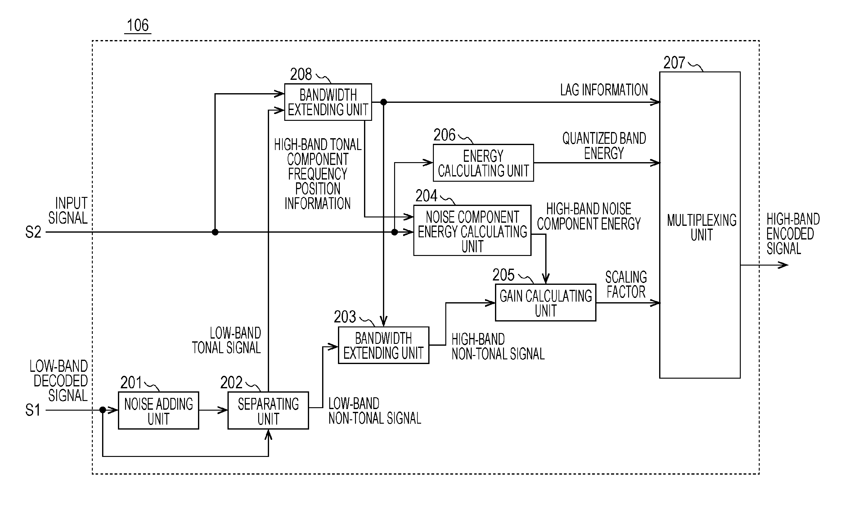
[0051]FIG. 3 is a block diagram illustrating a configuration of a second layer encoding unit 106 in this embodiment, differing from the second layer encoding unit 106 in the first embodiment in that the position relationship of the noise adding unit and the separating unit is inverted and that a separating unit 302 and a noise adding unit 301 are included.

[0052]From a low-band decoded signal S1, the separating unit 302 separates a low-band non-tonal signal, which is a non-tonal component, and a low-band tonal signal, which is a tonal component. The separation method used is the same as that in the description of the first embodiment, and the separation is performed accordi...

third embodiment

[0064]FIG. 5 is a block diagram illustrating a configuration of a voice signal decoding device according to a third embodiment. As an example, in the following description, an encoded signal is a signal that has a layered configuration including a plurality of layers and that is transmitted from an encoding device, and the decoding device decodes this encoded signal. Note that an example in which an encoded signal does not have a layered configuration will be described with reference to FIG. 8.

[0065]A decoder 400 illustrated in FIG. 5 includes a demultiplexing unit 401, a first layer decoding unit 402, and a second layer decoding unit 403. An antenna, which is not illustrated, is connected to the demultiplexing unit 401.

[0066]From an encoded signal input through the antenna, which is not illustrated, the demultiplexing unit 401 demultiplexes a low-band encoded signal, which is a first encoded signal, and a high-band encoded signal. The demultiplexing unit 401 outputs the low-band en...


PUM


Abstract

An encoding device according to the disclosure includes a first encoding unit that generates a first encoded signal in which a low-band signal having a frequency lower than or equal to a predetermined frequency from a voice or audio input signal is encoded, and a low-band decoded signal; a second encoding unit that encodes, on the basis of the low-band decoded signal, a high-band signal having a band higher than that of the low-band signal to generate a high-band encoded signal; and a first multiplexing unit that multiplexes the first encoded signal and the high-band encoded signal to generate and output an encoded signal. The second encoding unit calculates an energy ratio between a high-band noise component, which is a noise component of the high-band signal, and a high-band non-tonal component of a high-band decoded signal generated from the low-band decoded signal and outputs the ratio as the high-band encoded signal.

Description

BACKGROUND[0001]1. Technical Field[0002]The present disclosure relates to a device that encodes a voice signal and an audio signal (hereinafter referred to as a voice signal and the like) and a device that decodes the voice signal and the like.[0003]2. Description of the Related Art[0004]A voice encoding technology that compresses the voice signal and the like at a low bit rate is an important technology that realizes efficient use of radio waves and the like in mobile communication. In addition, expectations for a higher quality telephone voice have been raised in recent years, and a telephone service with enhanced realistic sensation has been desired. In order to realize this, it is sufficient that the voice signal and the like having a wide frequency band is encoded at a high bit rate. However, this approach contradicts efficient use of radio waves or frequency bands.[0005]As a method that encodes a signal having a wide frequency band at high quality at a low bit rate, there is a...

Claims


Application Information

Patent Timeline
Patent Type & Authority Applications(United States)
IPC IPC(8): G10L19/02G10L19/028G10L19/035
CPCG10L19/0208G10L19/028G10L19/035G10L21/038G10L19/02H03M7/30
Inventor NAGISETTY, SRIKANTHLIU, ZONG XIANEHARA, HIROYUKI
Owner FRAUNHOFER GESELLSCHAFT ZUR FOERDERUNG DER ANGEWANDTEN FORSCHUNG EV