Fusion Reactor

a fusion reactor and reactor technology, applied in nuclear reactors, nuclear engineering, greenhouse gas reduction, etc., can solve the problems of wasteful redistribution of kinetic energy, difficulty in producing fusion reactions at room temperature, particle collision likelihood, etc., and achieve the effect of increasing the likelihood of fusion reactions resulting from ion collisions

Active Publication Date: 2016-11-17
SPECTRE ENTERPRISES
View PDF7 Cites 1 Cited by
  • Summary
  • Abstract
  • Description
  • Claims
  • Application Information

AI Technical Summary

Benefits of technology

[0012]A method of perpetuating a fusion reaction is also disclosed. The method includes providing a positive electrode as well as a negative electrode, and applying a potential difference between the positive electrode and the negative electrode. A columnating panel is provided between the positive electrode and the negative electrode. The columnating panel has an atomic crystal structure defining a plurality of substantially straight channels therein. A flow of ions is initiated from the positive electrode, through the columnating panel, and to the negative electrode. Ions passing through the channels in the columnating panel follow paths determined by the channels, so that subsequent ions passing through the channels follow substantially the same path as previous ions. Therefore, subsequent ions strike the negative electrode at locations wherein previous ions are disposed on the negative electrode, thus increasing a likelihood of fusion reactions resulting from ion collisions.

Problems solved by technology

Successfully producing fusion reactions at room temperature remains a challenge when utilizing prior art techniques.
The proximity to the center of the reactor results in a likelihood of collisions between the particles.
The deuterium atmosphere causes many sub-threshold collisions and results in wasteful redistribution of kinetic energy.
There is a further need for a fusion reactor having a means of directing ions towards locations wherein there is a heightened probability of other ions therein, thus increasing the likelihood of fusion producing collisions.
Therefore, subsequent ions strike the negative electrode at locations wherein previous ions are disposed on the negative electrode, thus increasing a likelihood of fusion reactions resulting from ion collisions.

Method used


Image

  • Fusion Reactor
  • Fusion Reactor
  • Fusion Reactor

Examples


Embodiment Construction

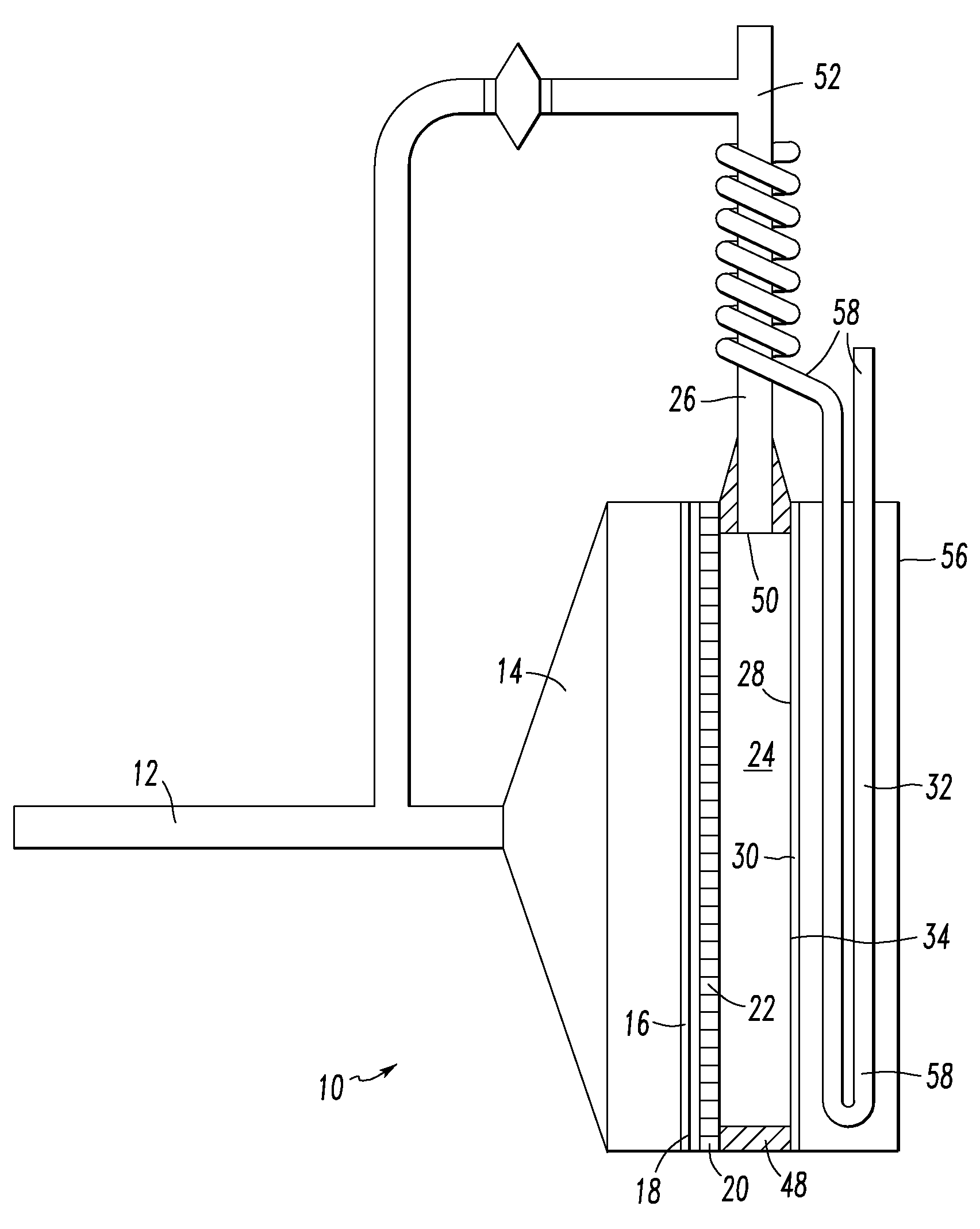
[0021]Referring to FIG. 1, a fusion reactor is illustrated. The fusion reactor 10 includes a gas inlet 12 for inserting deuterium gas into the system. The gas inlet 12 is connected to a funnel 14 that terminates in a positive electrode 16 at the wide exit 18 of the funnel 14. A columnating panel 20, which will be described in greater detail below, is disposed adjacent to the positive electrode 16. The exit face 22 of the columnating panel 20 is disposed next to a reduced pressure chamber 24, wherein pressure may be reduced by the vacuum system 26. The opposite side of the vacuum chamber 24 is formed by the target face 28 of the negative electrode 30. A heat transfer system 32 abuts the opposing face 34 of the negative electrode 30.

[0022]The positive electrode 16 is made from a deuterium-porous material, so that deuterium ions that are inserted into the system through the gas inlet 12 may pass through the positive electrode 16, and be accelerated towards the negative electrode 30 by ...


PUM


Abstract

A fusion reactor includes a columnating panel disposed between the positive electrode and negative electrode for channeling deuterium ions along predetermined paths that are likely to lead to fusion-producing collisions with previous deuterium ions. Deuterium ions are introduced to the reactor adjacent to the positive electrode, and then pass from the columnating panel, through a reduced pressure chamber, and then proceed towards the negative electrode. Once the deuterium ions strike the negative electrode, they remain attached to the negative electrode so that subsequent deuterium ions following the same channels through the columnating panel are more likely to collide with them.

Description

CROSS REFERENCE TO RELATED APPLICATION[0001]This application claims the benefit of U.S. Provisional Patent Application No. 62 / 095,699, which was filed on Dec. 22, 2014, and entitled Fusion Reactor.[0002]TECHNICAL FIELD[0003]The present invention relates to nuclear fusion reactors. More specifically, a means of guiding electrons and ions towards locations having a higher probability of collisions and reactions is provided.BACKGROUND INFORMATION[0004]Producing a fusion reaction utilizing prior art methods requires accelerating ions at sufficient speed for the reaction to occur in an environment having a sufficiently high ion density so that collisions between ions and resulting fusion occurs with useful frequency. Maintaining this ion density has been attempted by confining the ions utilizing various combinations of electric potential differences, magnetic fields, acoustic waves, and inertia. Many prior art systems rely on injecting ions into concentric electrode structures in an effo...

Claims


Application Information

Patent Timeline
Patent Type & Authority Applications(United States)
IPC IPC(8): G21B3/00
CPCG21B3/006G21B3/002Y02E30/10H05H3/06H05H2007/007
Inventor MOHLER, JONATHAN
Owner SPECTRE ENTERPRISES
Why Eureka
Try Eureka