Image Printing Apparatus and Method for Controlling an Image Printing Apparatus

Active Publication Date: 2016-11-17
BROTHER KOGYO KK
View PDF4 Cites 1 Cited by
  • Summary
  • Abstract
  • Description
  • Claims
  • Application Information

AI Technical Summary

Benefits of technology

[0006]In the known image forming system, for example, the image forming apparatus may receive two (2) preparation commands transmitted from two (2) image processing apparatuses successively in a short range of time, or almost at the same time. The image formi

Problems solved by technology

However, in order to comply with this cancellation method, processes to be executed by t

Method used


Image

  • Image Printing Apparatus and Method for Controlling an Image Printing Apparatus
  • Image Printing Apparatus and Method for Controlling an Image Printing Apparatus
  • Image Printing Apparatus and Method for Controlling an Image Printing Apparatus

Examples


first embodiment

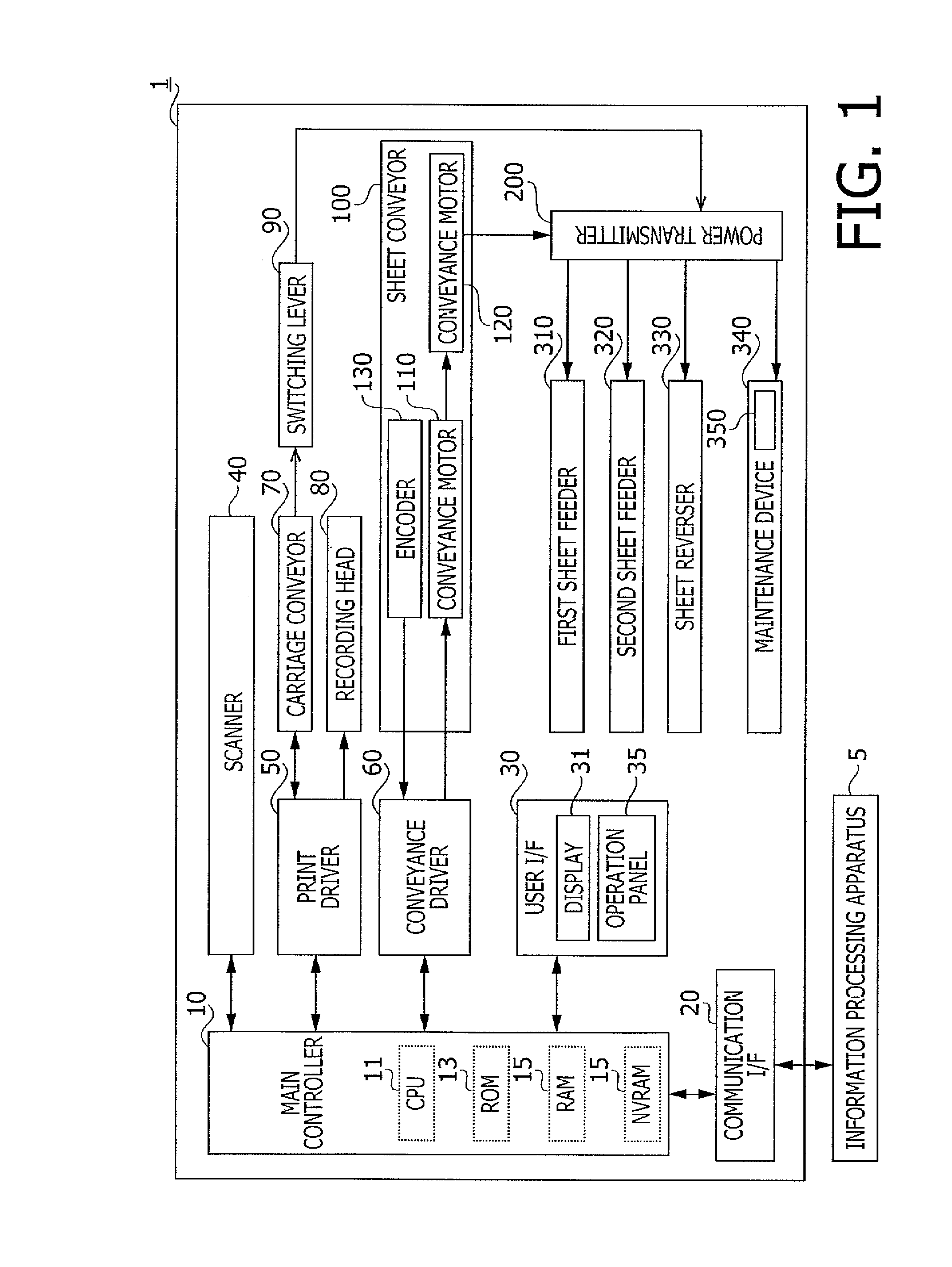
[0029]In a first embodiment, an image printing apparatus 1 shown in FIG. 1 has a plurality of functions including a printing function, to form an image on a sheet, and a copying function, to read an image of an original sheet and form a copied image of the read image. In other words, the image printing apparatus 1 includes a printer and a copier. The image printing apparatus 1 includes a main controller 10, a communication interface (I / F) 20, a user interface (I / F) 30, a scanner 40, a print driver 50, and a conveyance driver 60.

[0030]The image printing apparatus 1 further includes carriage conveyor 70, a recording head 80, a switching lever 90, a sheet conveyor 100, a power transmitter 200, a first sheet feeder 310, a second sheet feeder 320, a sheet reverser 330, and a maintenance device 340.

[0031]The main controller 10 includes a central processing unit (CPU) 11, a ROM 13, a RAM 15, and a non-volatile RAM (NVRAM) 17. The ROM 13 is configured to store various programs. The NVRAM 17...

second embodiment

[0144]Next, the image printing apparatus 1 according to a second embodiment will be described below. The image printing apparatus 1 in the second embodiment is configured to be similar to the image printing apparatus 1 in the first embodiment but is different in some aspects, which will be described below. In the following description, explanation of items and structures in the image printing apparatus 1 which are identical or equivalent to those described with regard to the image printing apparatus 1 in the first embodiment will be omitted.

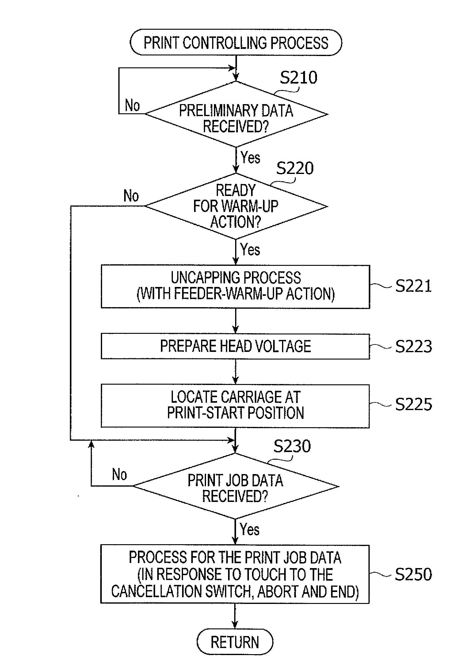
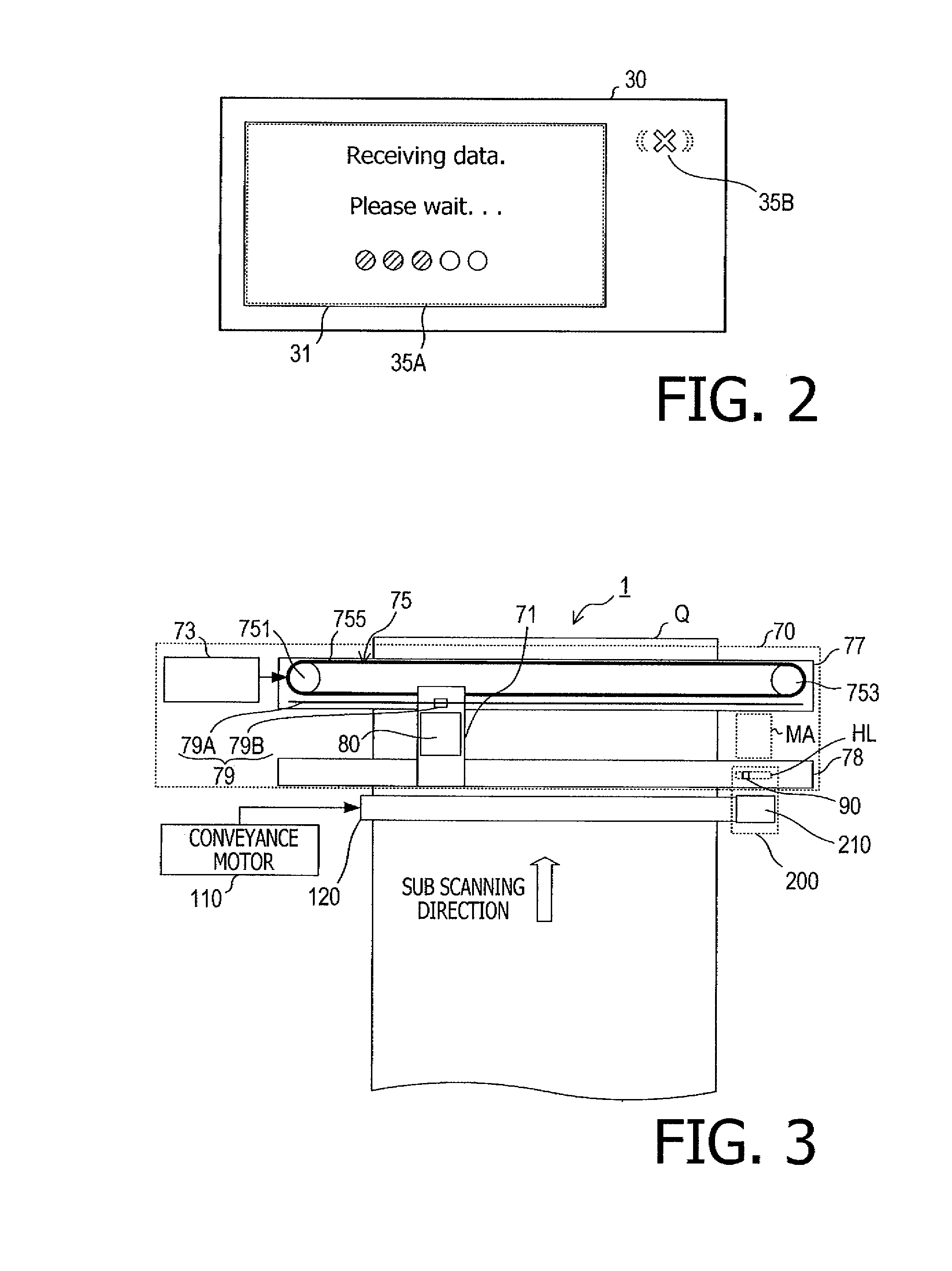
[0145]The image printing apparatus 1 in the second embodiment is configured to execute a predetermined notifying action, by executing a receipt-display process shown in FIG. 12, in place of the receipt-display process (see FIG. 8) in the first embodiment.

[0146]The receipt-display process includes step S610, which is an additional step to the receipt-display process in the first embodiment. Therefore, in response to receipt of the preliminary data...

third embodiment

[0152]Next, the image printing apparatus 1 according to the third embodiment will be described below. The image printing apparatus 1 in the third embodiment is configured to be similar to the image printing apparatus 1 in the first embodiment but is different in some aspects, which will be described below. In the following description, explanation of items and structures in the image printing apparatus 1 which are identical or equivalent to those described with regard to the image printing apparatus 1 in the first embodiment will be omitted.

[0153]The image printing apparatus 1 in the third embodiment is equipped with a user interface 500, as shown in FIG. 14, in place of the user interface 30. The user interface 500 is in a configuration such that a lamp 510 is added to the user interface 30.

[0154]The image printing apparatus 1 in the third embodiment is configured to execute a notifying action using the lamp 510, by executing a receipt-display process shown in FIG. 12, in place of ...


PUM


Abstract

An image printing apparatus including a communication interface, a printer, a user interface including an operation panel, a controller configured to control the printer and the user interface is provided. The controller is configured to receive preliminary data sent from an information processing apparatus through the communication interface; control the printer to perform a warm-up action; receive job data including image data through the communication interface; control the user interface to perform a receipt-notification and control the printer to start printing based on the image data; during a period from the receipt of the preliminary data until start of receiving the job data, withhold from accepting a cancellation command sent in response to user entering a cancellation operation; and after the start of receiving the job data, accept the cancellation command and cancel printing of the image based on the job data associated with to the entered cancellation command.

Description

CROSS-REFERENCE TO RELATED APPLICATION[0001]This application claims priority under 35 U.S.C. §119 from Japanese Patent Application No. 2015-098160 filed on May 13, 2015. The entire subject matter of the application is incorporated herein by reference.BACKGROUND[0002]1. Technical Field[0003]The following description relates to one or more aspects of an image printing apparatus and a method for controlling an image printing apparatus.[0004]2. Related Art[0005]An image printing apparatus, or an image forming apparatus, capable of conducting an image forming operation to form an image on a sheet according to image data, which may be transmitted from an information processing apparatus, is known. In an image forming system, a preparation command for the image forming apparatus to prepare for the image forming operation may be transmitted from the information processing apparatus to the image forming apparatus prior to transmission of the image data. The image forming apparatus in the ima...

Claims


Application Information

Patent Timeline
IPC IPC(8): H04N1/00G06F3/12
CPCH04N1/00931H04N1/0049G06F3/1253G06F3/121G06F3/1235G06F3/1204G06F3/126G06F3/1274G06F3/1285G06F3/1207G06F3/1259G06F3/1268G06K15/1818G06K15/1821
Inventor OGUCHI, TOMOYA
Owner BROTHER KOGYO KK
Why Eureka
Try Eureka