Nonlinear distortion compensating receiver and nonlinear distortion compensation method

a receiver and nonlinear distortion technology, applied in the direction of oscillator generators, digital transmission, pulse techniques, etc., can solve the problems of deteriorating linearity of analogue circuits, and achieve the effect of simple circuit configuration

Inactive Publication Date: 2014-02-18
PANASONIC CORP
View PDF7 Cites 1 Cited by
  • Summary
  • Abstract
  • Description
  • Claims
  • Application Information

AI Technical Summary

Benefits of technology

[0016]According to the present invention, digital signal processing can perform the generation of a replica signal of a distortion component and adaptive filtering, so that it is possible to adaptively compensate for nonlinear distortion with a simple circuit configuration. Especially, it is possible to precisely cancel a distortion component of a neighboring interfering wave signal. Furthermore, since a desired wave is no included in a generation circuit of a replica signal of a distortion component, it is possible to perform distortion compensation precisely, regardless of presence or absence, and the strength of a desired wave.

Problems solved by technology

Although the power supply voltage has been lowered following the development of semiconductor process, it is widely known that the linearity of an analogue circuit is deteriorated due to the reduction of the power supply voltage.

Method used


Image

  • Nonlinear distortion compensating receiver and nonlinear distortion compensation method
  • Nonlinear distortion compensating receiver and nonlinear distortion compensation method
  • Nonlinear distortion compensating receiver and nonlinear distortion compensation method

Examples


embodiment 1

[0026](Embodiment 1)

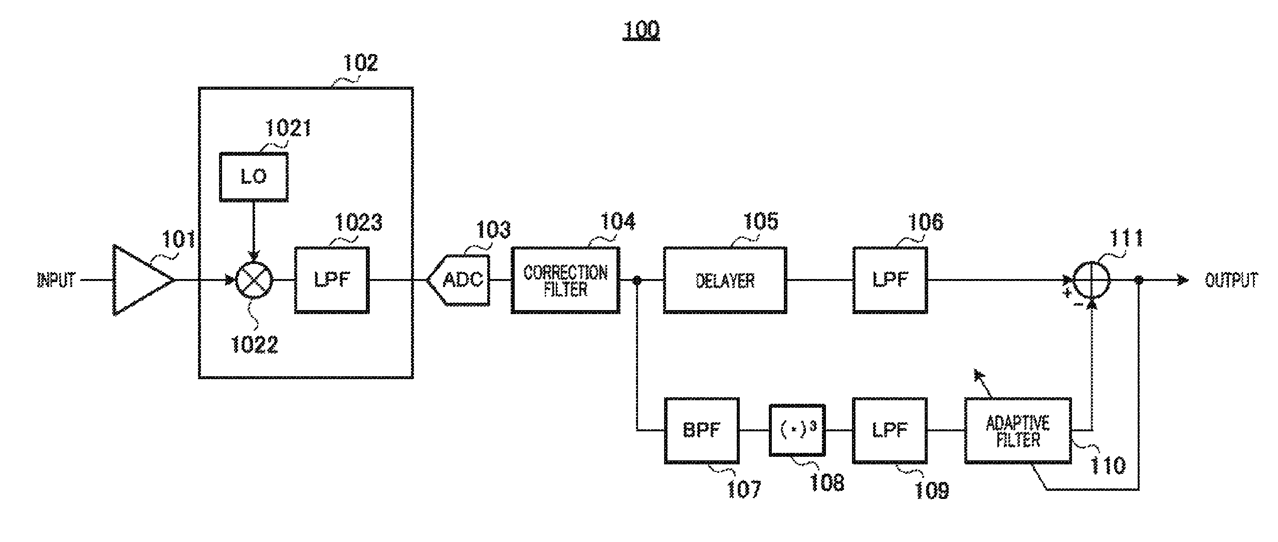
[0027]FIG. 3 is a block diagram showing a main configuration of a nonlinear distortion compensation receiver according to embodiment 1 of the present invention.

[0028]LNA 101 amplifies an input signal. LNA 101 outputs the amplified signal to direct sampling mixer (DSM) 102.

[0029]Direct sampling mixer 102 includes LO 1021, mixer 1022, and LPF 1023, frequency-converts (down-converts) the amplified signal into a low frequency, and band-limits the signal after frequency conversion. Specifically, mixer 1022 frequency-converts an amplified signal into a low frequency by multiplying a local frequency signal output from LO 1021 and an amplified signal output from LNA 101. LPF 1023 band-limits a frequency-converted signal, and, by this means, direct sampling mixer 102 performs direct sampling to an amplified signal output from LNA 101. Direct sampling mixer 102 outputs the signal after direct sampling to ADC 103.

[0030]ADC 103 is provided in a rear stage of direct sampling ...

embodiment 2

[0046](Embodiment 2)

[0047]Embodiment 1 has described a direct conversion receiver (DCR). The present embodiment will describe a low intermediate frequency (low-IF) receiver.

[0048]FIG. 4 is a block diagram showing a main configuration of a nonlinear distortion compensation receiver according to embodiment 2 of the present invention. In a nonlinear distortion compensation receiver according to the present embodiment of FIG. 4, the same components as FIG. 3 will be assigned the same reference numerals as FIG. 3 and their explanations will be omitted. Nonlinear distortion compensation receiver 200 of FIG. 4 employs a configuration that adds frequency converter 201 to nonlinear distortion compensation receiver 100 of FIG. 3.

[0049]Frequency converter 201 is provided in a rear stage of correction (inverse characteristic) filter 104 and converts a signal after a correction filter into a zero IF signal. Frequency converter 201 separates the zero IF converted signal into a main path that is t...

embodiment 3

[0053](Embodiment 3)

[0054]Embodiment 1 and embodiment 2 have been explained on the premise that adaptive filter 110 generates the replica path signal and is arranged to a replica path is a linear filter. The present embodiment will describe a case where an adaptive filter arranged to the replica path is a nonlinear adaptive filter.

[0055]FIG. 5 is a block diagram showing a main configuration of a nonlinear distortion compensation receiver according to embodiment 3 of the present invention. In a nonlinear distortion compensation receiver according, to the present embodiment of FIG. 5, the same components as FIG. 3 will be assigned the same reference numerals as FIG. 3 and their explanations will be omitted. Compared to nonlinear distortion compensation receiver 100 of FIG. 3, nonlinear distortion compensation receiver 300 of FIG. 5 employs a configuration that removes correction (inverse characteristic) filter 104, cubic circuit 108, and adaptive filter 110, and adds nonlinear adaptiv...


PUM


Abstract

Disclosed are a nonlinear distortion compensating receiver and nonlinear distortion compensation method, wherein nonlinear distortion is reduced with a simple circuit configuration. A correction (opposite characteristics) filter (104) has characteristics opposite that of the frequency characteristics of a direct sampling mixer (102) and corrects signals sampled by the direct sampling mixer (102). In the main path, a LPF (106) extracts a frequency band component of a desired signal from the corrected signal. In the replica path, a BPF (107) extracts the frequency band component of a blocker signal from the corrected signal. A cubing circuit (108) uses the frequency band component of the blocker signal to generate a replica signal for the nonlinear distortion. An adaptive filter (110) performs filter processing on the replica signal while updating the filter coefficients. A subtractor (111) subtracts the output signal of the adaptive filter (110) from the frequency band component of the extracted desired signal and outputs the subtraction result as the desired signal.

Description

TECHNICAL FIELD[0001]The present invention relates to nonlinear distortion compensation receiver and nonlinear distortion compensation method for adaptively compensating nonlinear distortion.BACKGROUND ART[0002]In recent years, miniaturization and low power consumption of a radio communication apparatus have been developed. Although the power supply voltage has been lowered following the development of semiconductor process, it is widely known that the linearity of an analogue circuit is deteriorated due to the reduction of the power supply voltage. Furthermore, many radio standards, such as an integrated services digital broadcasting-terrestrial (ISDB-T), is required to receive even under the condition where a strong neighboring interfering wave is present. Therefore, there is a growing demand for distortion compensation in order to improve the linearity at a receiver.[0003]There is a conventional distortion compensation receiver shown in FIG. 1 (for example, see non-patent literat...

Claims


Application Information

Patent Timeline
Patent Type & Authority Patents(United States)
IPC IPC(8): H04B1/10
CPCH04B1/0028H04B1/123H04L27/3863H04B1/109
Inventor TSUKAMOTO, SATOSHISAITO, NORIAKISHIMIZU, YOSHITOMORITA, TADASHIABE, KATSUAKI
Owner PANASONIC CORP
Why Eureka
Try Eureka