
Noise suppression

a technology of noise suppression and noise reduction, applied in the field of noise suppression, can solve the problems of audio noise problems such as “burst noise”, burst noise exists in the audio channel, and can be really annoying, and achieve the effect of preserving voice quality, continuous burst noise suppression, and convenient pcb routing

Inactive Publication Date: 2014-03-25
TELEFON AB LM ERICSSON (PUBL)
View PDF12 Cites 1 Cited by
  • Summary
  • Abstract
  • Description
  • Claims
  • Application Information

AI Technical Summary

Benefits of technology

The present invention is a more effective and efficient method for reducing background noise while maintaining good speech quality. This method is able to cancel out burst noise that occurs during radio state changes, such as when switching between different radios. By cancelling out burst noise, the method makes it easier to design the circuit board of the device and may even remove some components.

Problems solved by technology

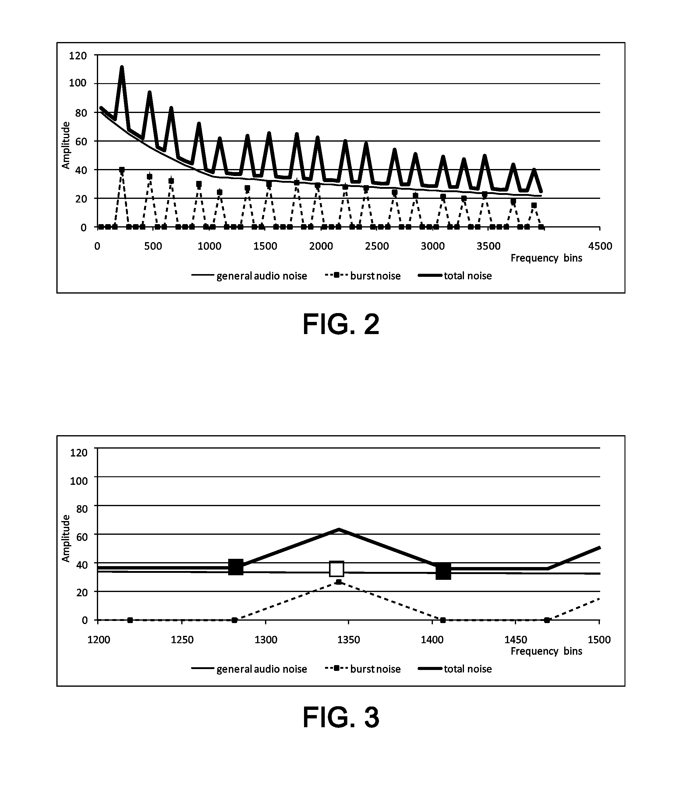
In a system where radio signal bursts are present while having audio channel open, a common audio noise problem appears called “burst noise” or “time division multiplexing access (TDMA) noise”.
This problem is particularly present on uplink paths where a microphone is the electrical source of audio.
The burst noise can be really annoying and advantageously has to be removed.
This burst noise exists in the audio channel due to two common coupling mechanisms used in radio transmissions:A radio power amplifier consumes significant amount of current when transmitting while the current consumption is very low when not transmitting.
This current consumption variation is creating a voltage variation on the battery supply for the entire product due to battery impedance.
This results in an audio noise coupled with the radio power amplifier activities.
Thus, a radio activity comprising signal bursts is by itself creating noise on the audio path.
This results in non-fixed coupling gains meaning a non-fixed level of burst noise.
If this coupling gain is low enough, the resulting burst noise could be low enough not to be heard.
This method has the disadvantage that the addition of passive components and efficient power supply paths has a cost.
The routing of audio lines on PCB can be very painful.
On some products, because of their size and mechanic arrangement, it is even not possible to remove completely the burst noise.
However, this method also has a drawback, namely because of the filter insertion, the voice signal itself suffers attenuation on the rejected frequencies.
For this reason, the voice quality can be significantly damaged.
This results in the cancellation of noise even with presence of a speech signal.
When a phone is operating in discontinuous transmission mode, the spectrum of the noise is no more constant and the noise suppressor is not be able to correctly estimate it, resulting in non efficient cancellation.
Furthermore, GSM / GPRS / EDGE phones can adapt suddenly the power of their radio transmission resulting in a new spectrum composition of the burst noise.
This drives also to a bad estimation of noise by the noise suppressor resulting in a suboptimal noise cancellation.
So, the noise suppressor cannot take into account sudden spectral changes.
For this reason, the noise suppressor does not work properly in systems based on GPRS (because several time slots can be used for transmission in one frame) or in some 3G systems (because of too complex and non-constant spectrum).

Method used


Image

  • Noise suppression
  • Noise suppression
  • Noise suppression

Examples


first embodiment

[0032]In the first embodiment, the idea is based on the noise suppressor of which operation was briefly explained earlier. In fact, the proposed noise suppression method is by essence adaptive and would then track the variation of burst noise level or spectrum linked to variation of phone local environment.

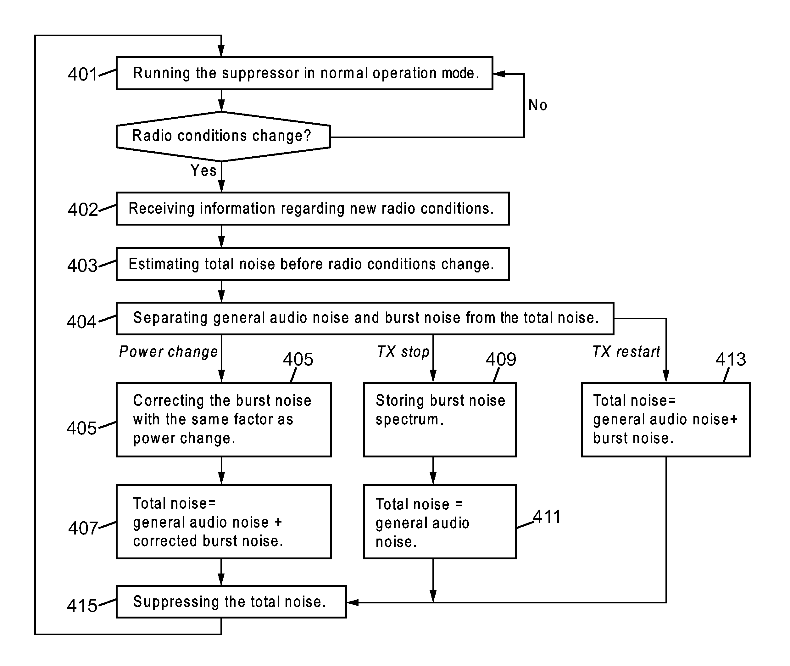
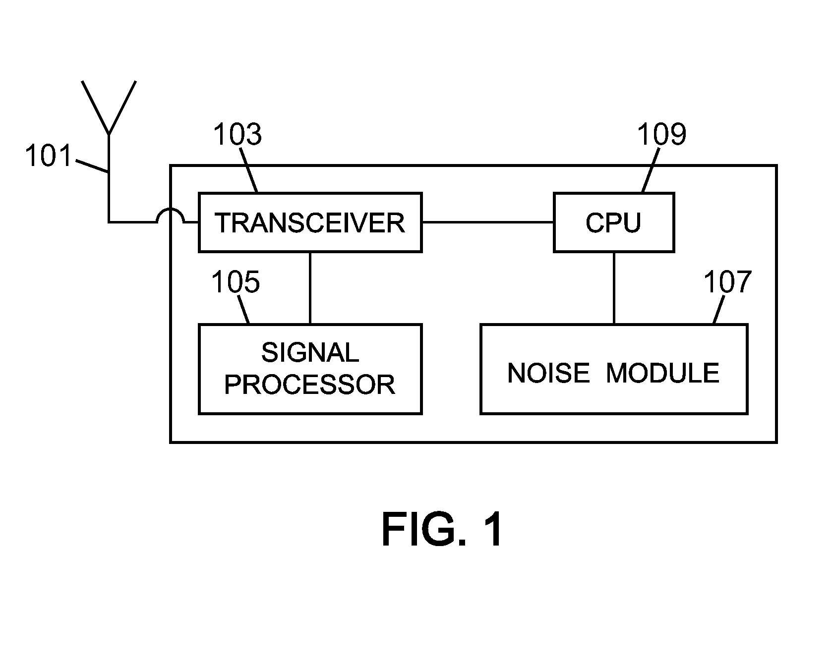
[0033]The idea consists in forwarding to the noise module 107, in this case called noise suppressor, some information regarding the radio transmission in terms of radio activity (informing about continuous / discontinuous transmission) and in terms of radio transmission power. This information is then treated by the noise suppressor 107 to predict a correction for the estimated noise. Because in the present invention the estimated noise will track the variation of radio transmission, the noise suppression will be continuous on the burst noise itself.

[0034]The GSM / GPRS / EDGE phone protocol stack, in particular the layer 1 protocol layer, knows well what the radio transmission activity...

second embodiment

[0058]the present invention is described next with reference to the flow chart of FIG. 5. The idea is based on an adaptive filter, i.e. the noise module 107, trained to match a coupling transfer function between radio activities and an audio path. The key is to feed this filter with a synthesised or probed signal representing in time the radio activity. The output of the filter is subtracted from the audio path.

[0059]Considering that RF is the radio output level in time, F is the radio to audio coupling transfer function, we can write B as the radio coupled audio noise: B=F(RF). The audio path itself contains this noise but also the useful audio signal called S, so the audio path signal A is A=S+B=S+F(RF) which represents a useful signal with radio coupled audio noise.

[0060]In step 501 the filter receives information regarding new radio conditions. In step 502 a synthesised signal RF′ is obtained which follows as close as possible the radio output level in time. Considering G being ...


PUM


Abstract

The present invention relates to a method of suppressing noise in a communication device. The idea consists in forwarding to a noise suppression module some information regarding the radio transmission in terms of radio activity and / or in terms of radio transmission power. The module then advantageously uses this information to suppress radio path noise.

Description

TECHNICAL FIELD[0001]The present invention relates to a method of noise suppression. More specifically, the proposed method is able to suppress total noise, including burst noise on audio path. The invention equally relates to a corresponding module for suppressing noise, to mobile equipment comprising the module and to a computer program product comprising instructions for implementing the steps of the method.BACKGROUND OF THE INVENTION[0002]In a system where radio signal bursts are present while having audio channel open, a common audio noise problem appears called “burst noise” or “time division multiplexing access (TDMA) noise”. This problem is particularly present on uplink paths where a microphone is the electrical source of audio. In fact, microphone signal is very low, around mV, and any noise above μV can be heard. The burst noise can be really annoying and advantageously has to be removed.[0003]This burst noise exists in the audio channel due to two common coupling mechani...

Claims


Application Information

Patent Timeline
Patent Type & Authority Patents(United States)
IPC IPC(8): H04B1/04
CPCG10L21/0208G10L2021/02085
Inventor CIMAZ, LIONEL
Owner TELEFON AB LM ERICSSON (PUBL)
Learn More