Azimuthally tunable multi-zone electrostatic chuck

Active Publication Date: 2016-11-24
APPLIED MATERIALS INC
View PDF6 Cites 184 Cited by
  • Summary
  • Abstract
  • Description
  • Claims
  • Application Information

AI Technical Summary

Benefits of technology

[0009]Implementations described herein provide a method and apparatus for processing a substrate on a substrate support assembly which enables both lateral and azimuthal tuning of the heat transfer between an electrostatic chuck (ESC) and a substrate. The method includes processing a first substrate using a first temperature profile on the ESC having primary heaters and spatially tunable heaters. A deviation profile is determined from a result of pr

Problems solved by technology

Allowable CD variation across a substrate processed within a processing chamber is difficult to achieve due to chamber asymmetries such as chamber and substrate temperature, flow conductance, and RF fields.
In processes utilizing an electrostatic chuck, uniformity of temperature control across the surface of the substrate is even more challenging due to the non-homogeneous construction of the chuck below the substrate.
Since the structure of the electrostatic chuck can vary both laterally and azimuthally, uniformity of heat transfer between the chuck and substrate is complicated and very difficult to obtain, resu

Method used


Image

  • Azimuthally tunable multi-zone electrostatic chuck
  • Azimuthally tunable multi-zone electrostatic chuck
  • Azimuthally tunable multi-zone electrostatic chuck

Examples


first embodiment

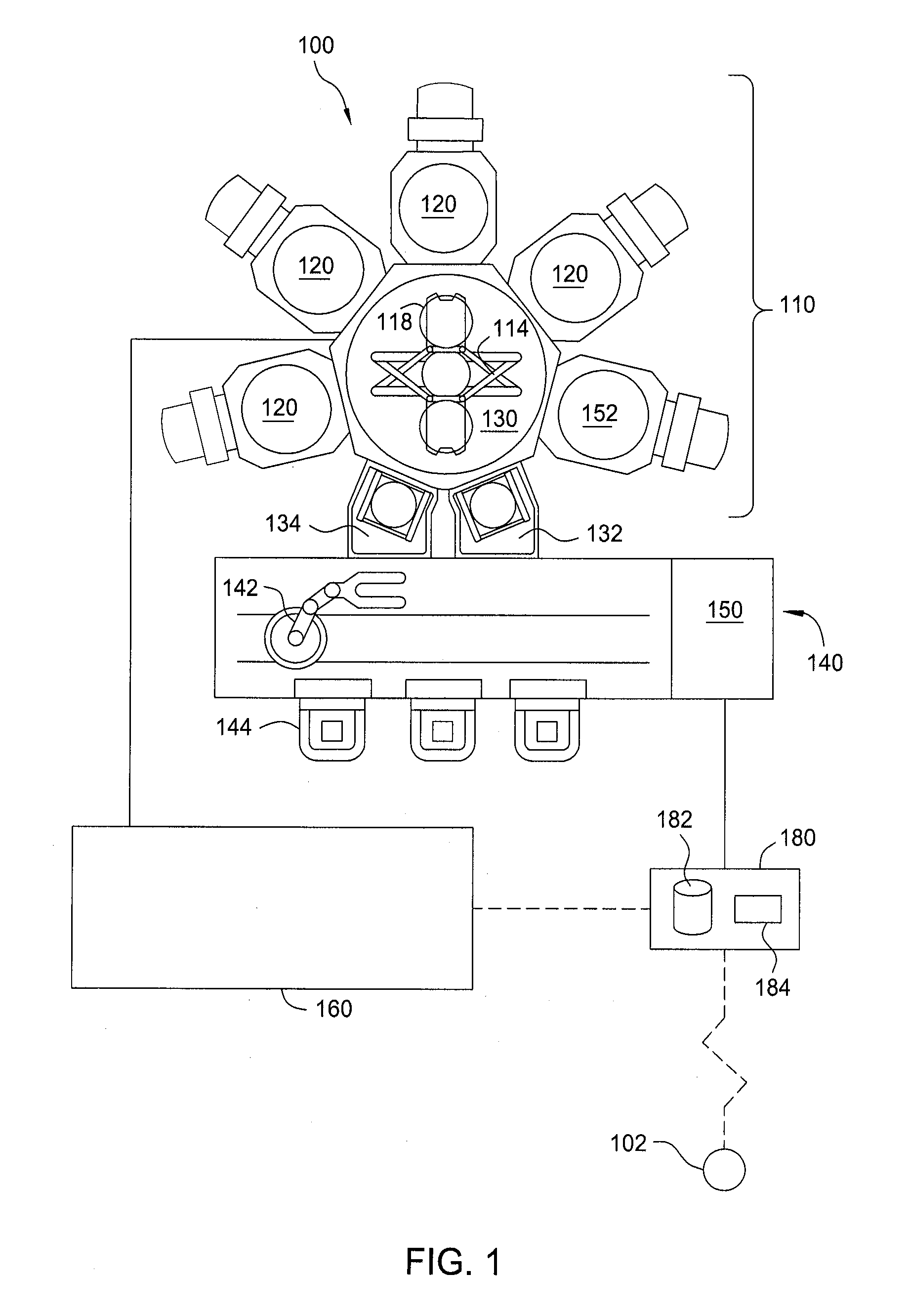
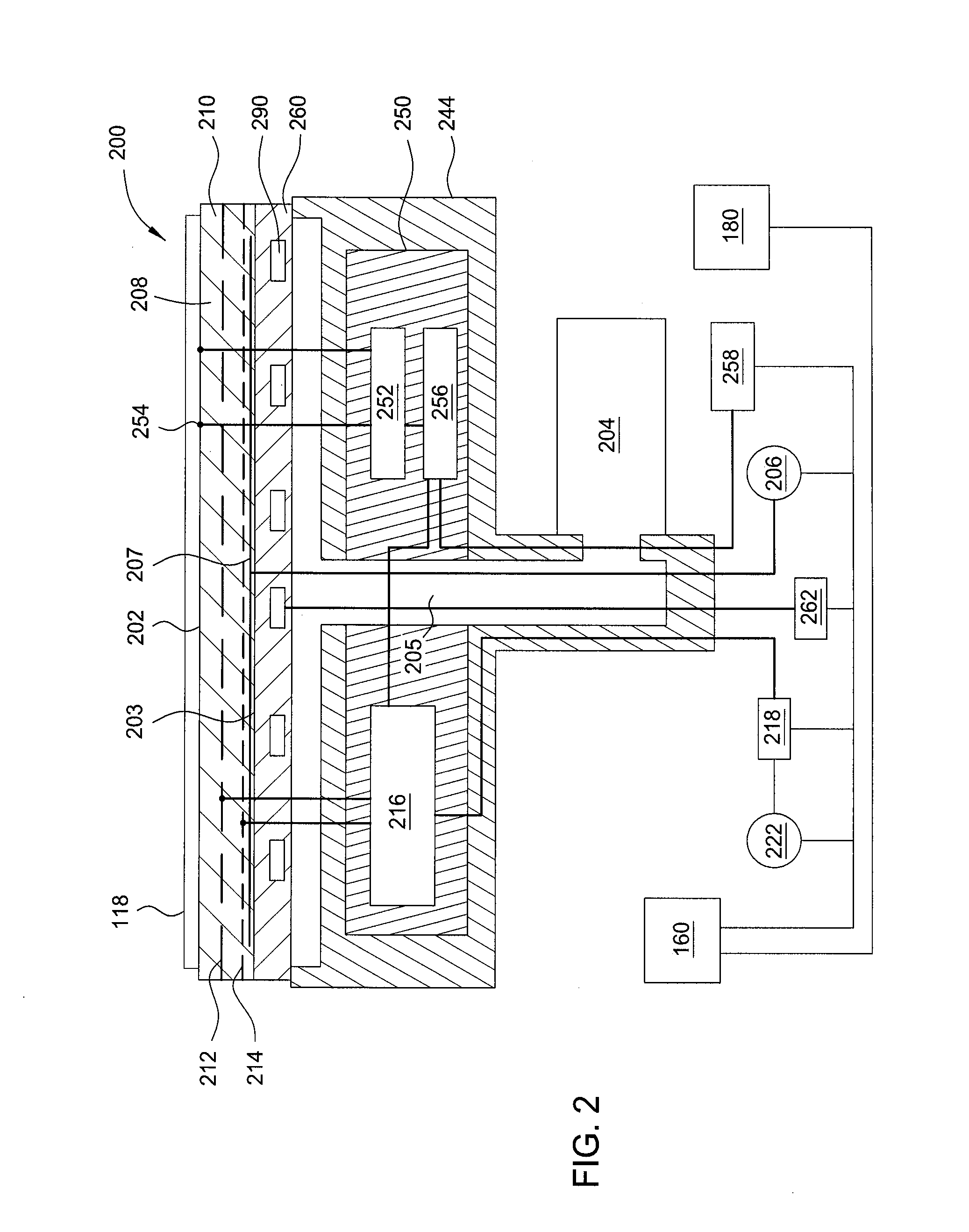
[0075]FIG. 5 is a flow diagram of a method 500 for processing a substrate using a process recipe wherein the process recipe is determined using a feedforward controller routine. The flow diagram may be implemented as a software routine on a computing device, such as described by system 400. The spatially tunable heaters are independently controllable and determine a temperature profile of substrates processed thereon. The controller may alter the heat generated by one spatially tunable heater relative another by controlling at least one or more of the duty cycle, voltage, current, duration of power applied separately to each individual spatially tunable heater relative another. The power supplied to the spatially tunable heaters may also be provides simultaneously between a plurality of heaters as described above, or alternatively, sequentially scanned across individual spatially tunable heaters. A work-piece, such as the substrate 118, may be processed on the substrate support ass...

second embodiment

[0080]FIG. 6 is a method 600 for processing a substrate using the spatially tunable heaters in conjunction a feedback controller routine. The process begins at operation 610 wherein the process sensitivity, target process data and kth run metrology process data are inputted into the iterative learning controller. At kth iteration (wherein k=1, 2, . . . ), a feedback controller routine is set up to have the inputs of the delta metrology data, i.e., the kth run metrology data, target process data, is applied to obtain the desired substrate temperature profile based on process to temperature sensitivity and substrate temp data. The feedback controller routine may be an iterative learning controller or other type of controller such as a LUT, PID, MPC or other suitable controller.

[0081]At operation 620, a desired substrate temperature offset map is determined from the inputted data. The desired substrate temperature offset map becomes an input for the controller to adjust the recipe para...


PUM


Abstract

Implementations described herein provide a method for processing a substrate on a substrate support assembly which enables both lateral and azimuthal tuning of the heat transfer between an electrostatic chuck and a substrate. The method includes processing a first substrate using a first temperature profile on the ESC having primary heaters and spatially tunable heaters. A deviation profile is determined from a result of processing the first substrate from a target result profile. The first temperature profile is adjusted to a second temperature profile on the ESC based on the deviation profile. Adjusting to the second temperature profile includes incrementing the power to one or more spatially tunable heaters in one or more discrete locations corresponding to the deviations profile. A second substrate is then processed on the ESC using the second temperature profile.

Description

CROSS-REFERENCE TO RELATED APPLICATIONS[0001]This application claims benefit of U.S. Provisional Application Ser. No. 61 / 165,572 filed May 22, 2015 (Attorney Docket No. APPM / 22925USL), which is incorporated by reference in its entirety.BACKGROUND[0002]1. Field[0003]Implementations described herein generally relate to semiconductor manufacturing and more particularly to real-time temperature control of an electrostatic chuck and method of using the same.[0004]2. Description of the Related Art[0005]As the feature size of the device patterns get smaller, the critical dimension (CD) requirements of these features become a more important criterion for stable and repeatable device performance. Allowable CD variation across a substrate processed within a processing chamber is difficult to achieve due to chamber asymmetries such as chamber and substrate temperature, flow conductance, and RF fields.[0006]In processes utilizing an electrostatic chuck, uniformity of temperature control across ...

Claims


Application Information

Patent Timeline
IPC IPC(8): H05B1/02H01L21/67H01L21/66H01L21/683
CPCH01L21/6833H05B1/0233H01L22/20H01L21/67103H01L21/67288H01L21/67248H01L21/67109H01L21/6831
Inventor ZHANG, CHUNLEICRIMINALE, PHILIPBABAYAN, STEVEN E.ULLSTROM, DAVID
Owner APPLIED MATERIALS INC
Why Eureka
Try Eureka