
Tunable liquid lens with reduced aberration

a liquid lens and aberration technology, applied in the field of liquid crystal lenses, can solve the problems of significant aberration and scattering drop, inconsistent optical properties of many tunable liquid crystal optical devices, and aberration inducing image distortion, so as to reduce the

Inactive Publication Date: 2009-08-27
POINT FINANCIAL
View PDF7 Cites 63 Cited by
  • Summary
  • Abstract
  • Description
  • Claims
  • Application Information

AI Technical Summary

Benefits of technology

"The patent text describes a new technology for tunable liquid crystal optical devices, such as lenses and beam steering devices. The technology involves using a variable electric field to change the orientation of liquid crystal molecules in the device, which results in a change in optical power. However, the optical properties of the device are not consistent over its tunable range. Aberration and scattering properties can increase as the electric field changes the orientation of the liquid crystal molecules. To address this issue, the technology proposes a method for measuring or detecting the aberration and scattering caused by the liquid crystal layer under conditions of lower or moderate electric fields to determine the optical quality of the device as a function of electric field. The electric field controller then sets an electric field control signal in response to the desired optical value, with an offset value restricting the range of operation to reduce the effect of aberration or scattering. The technology provides a tunable optical device with improved optical properties and reduced aberration and scattering."

Problems solved by technology

It has been discovered that the optical properties of many tunable liquid crystal optical devices are not consistent over their tunable range.
In the case of a lens, aberrations induce image distortions.
It has been found in the case of some lenses, aberration and scattering drop significantly after peak optical power of the tunable liquid crystal lens.
Thus, use of peak optical power of a tunable liquid crystal lens to enjoy maximum power and also the largest range of tunability may be less desirable than using a somewhat reduced range that avoids higher levels of aberration and scattering of the lens.

Method used


Image

  • Tunable liquid lens with reduced aberration
  • Tunable liquid lens with reduced aberration
  • Tunable liquid lens with reduced aberration

Examples


Embodiment Construction

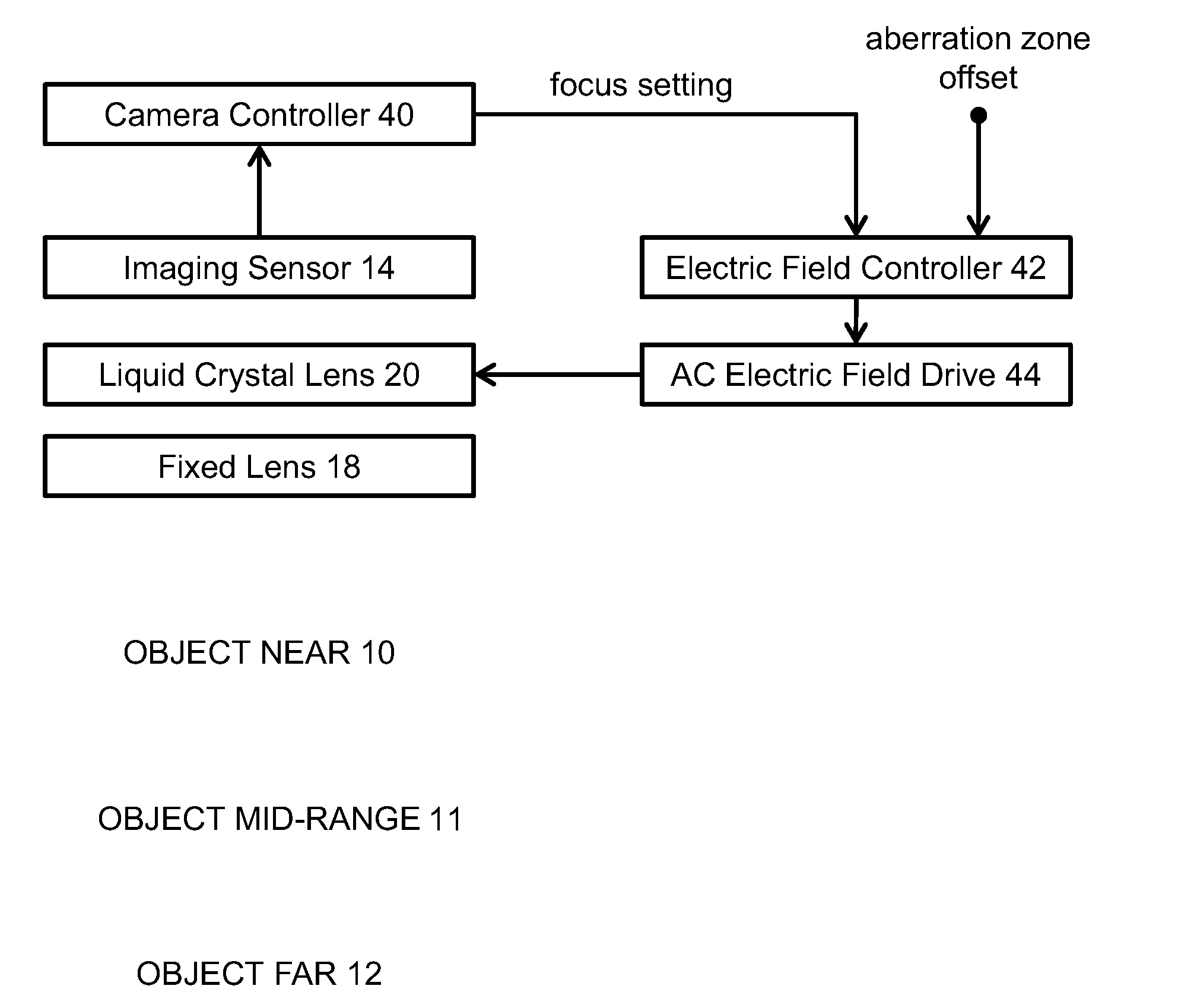
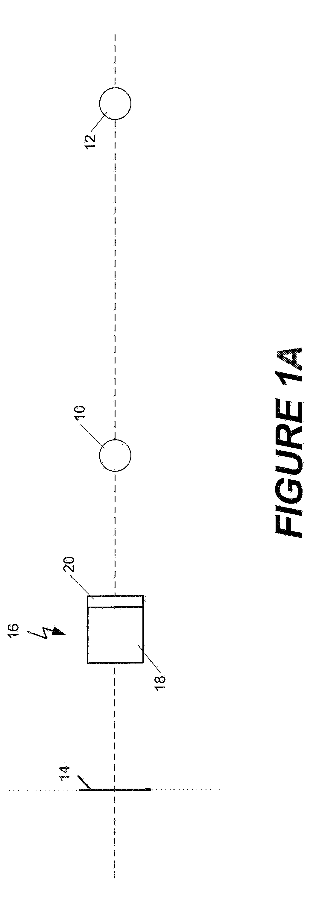
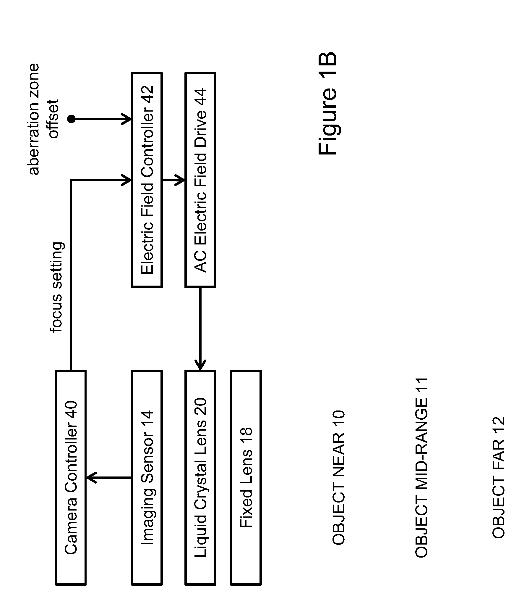
[0018]FIGS. 1A and 1B depict schematically a tunable imaging system using a tunable lens 16. Two or three objects to be imaged are shown in the figures, a “near” object 10 and a “far” object 12, in addition to a “mid-range” object 11. A two-dimensional image sensor (e.g., a photodetector) 14 is positioned at a fixed plane so as to capture the image formed by lens 16. The lens includes a fixed lens assembly 18 and a tunable liquid crystal (LC) lens 20. For a mobile telephone or laptop computer application, the assembly may be quite compact with the image sensor 14 and the liquid crystal and fixed lens assembly being about 5 millimeters thick. The LC lens is voltage-controlled and, in response to voltage changes which alter the electric field across the LC structure, the refractive index of the LC lens changes.

[0019]A camera controller 40 sets a desired focus value, and an electric field controller 42 determines a suitable control voltage value corresponding to the focus value. The co...


PUM

PropertyMeasurementUnit
thickaaaaaaaaaa
optical poweraaaaaaaaaa
electric fieldaaaaaaaaaa

Abstract

A tunable optical imaging system uses a fixed lens and a tunable liquid crystal lens that is operated only outside of an operational range of high aberration. A voltage range applied to change the optical power of the liquid crystal lens is limited to a continuous tunable range of low aberration. The relative positioning between the lens and a corresponding photodetector, and the relative lens powers of a fixed lens and the tunable lens, may be selected to compensate for any optical power offsets resulting from the limitation of the voltage range of the tunable lens. The lens may be operated in either positive tunability or negative tunability mode.

Description

TECHNICAL FIELD[0001]The present invention relates generally to the field of electrically controllable optical devices and, more particularly, to liquid crystal lenses having an optical power that is adjustable through a continuous range.BACKGROUND OF THE INVENTION[0002]Tunable liquid crystal optical devices are known in the art, as for example in WO / 2007 / 098602. These optical devices are flat structures having a liquid crystal layer in which the liquid crystal changes its refractive index as a function of the electric field. By applying a spatially modulated electric field, there is provided a spatially modulated index of refraction with the appropriate geometry for the optical device, for example a lens. Such tunable lenses offer the advantage of being thin and compact, a factor that is important in certain applications, such as in the case of mobile telephone cameras. The performance of such lenses can be measured by two important parameters, namely the tunable diopter range and ...

Claims


Application Information

Patent Timeline
Patent Type & Authority Applications(United States)
IPC IPC(8): G02F1/13
CPCG02B3/14G03B17/00G02F2001/291G02F1/291
Inventor GALSTIAN, TIGRANASATRYAN, KARENPRESNIAKOV, VLADIMIRZOHRABYAN, ARMENTORK, AMIRBAGRAMYAN, ARAM
Owner POINT FINANCIAL
Learn More