
Use of amplified spontaneous emission from a semiconductor optical amplifier to minimize channel interference during initialization of an externally modulated DWDM transmitter

Inactive Publication Date: 2005-01-11
CIENA
View PDF2 Cites 61 Cited by
  • Summary
  • Abstract
  • Description
  • Claims
  • Application Information

AI Technical Summary

Benefits of technology

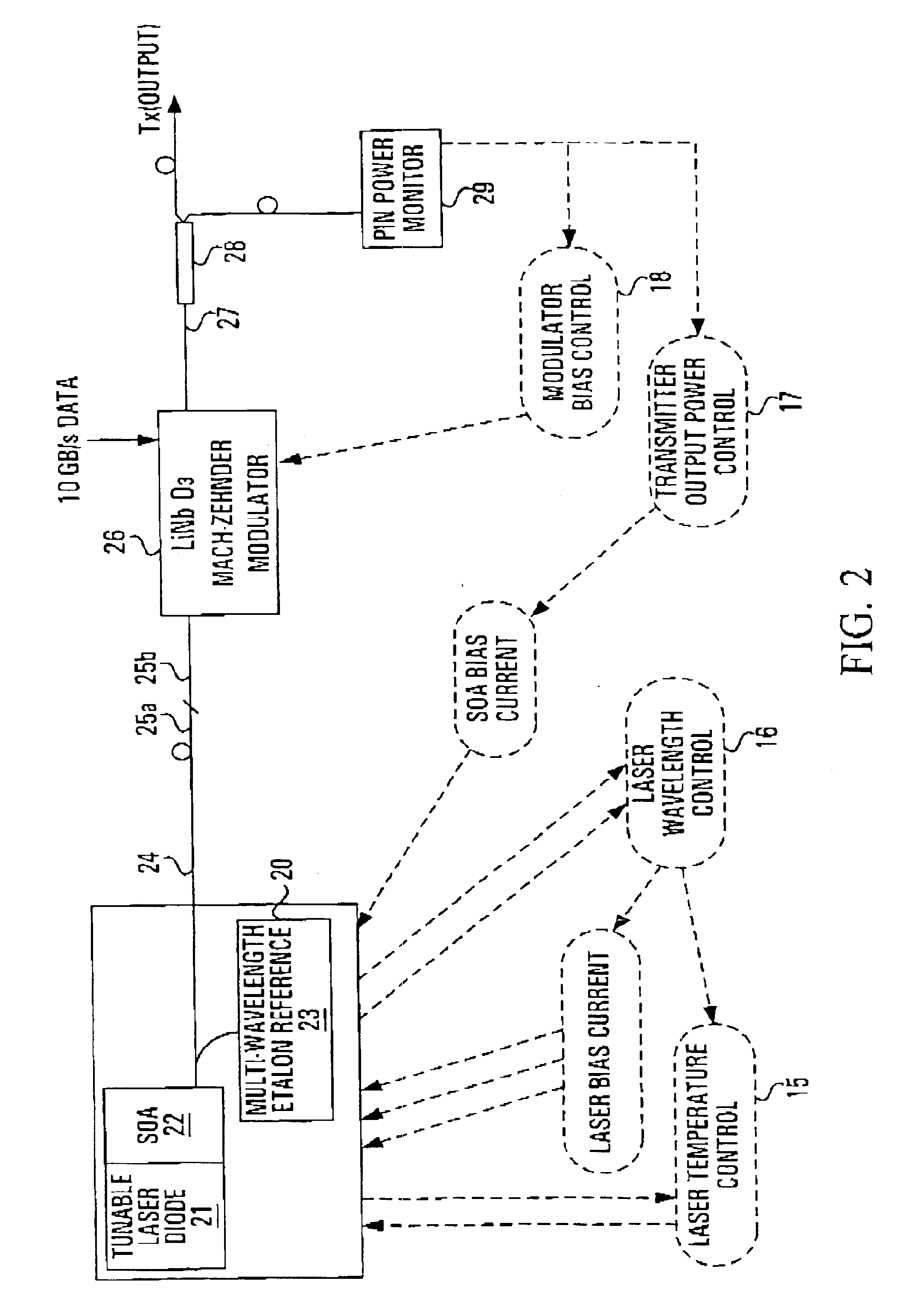
The external modulator is biased to the point of minimum transmission (as determined above) so that the transmitter output power may be reduced during laser turn-on and laser wavelength tuning. The SOA is turned off to provide attenuation as the laser is turned on or during laser wavelength tuning. This allows the laser wavelength to stabilize without interfering with adjacent DWDM channels. The SOA gain can also be used to control the optical output power of the transmitter. In addition, a small signal modulation may also be applied to the SOA bias for the purposes of channel identification.

Problems solved by technology

Modulating the output intensity of a semiconductor laser diode using excitation current typically results in spectral broadening (chirping) of the transmitted optical signal.
This chirping limits the tolerance of the optical signal to fibre dispersion and, therefore, limits the transmission distance and / or bit-rate of the system.
Lithium niobate has a large temperature coefficient of expansion which can result in an effective imbalance in optical path length between the two arms of a Mach-Zehnder interferometer.
This search results in optical power transients during transmitter card initialization.
However, this technique has two limitations.
This technique cannot be applied if the CW light source is a tunable laser diode which uses the laser operating temperature as a wavelength tuning mechanism.
Secondly, it may not be possible to reduce the laser output power sufficiently to eliminate the effects of optical power transients on the system.
The single wavelength laser diodes used in most transmitter realizations to date are usually of sufficient power such that the use of optical amplifiers to boost the optical signal is not warranted.
The wavelength and output power of such transmitters are not readily controllable as mentioned above.

Method used


Image

  • Use of amplified spontaneous emission from a semiconductor optical amplifier to minimize channel interference during initialization of an externally modulated DWDM transmitter
  • Use of amplified spontaneous emission from a semiconductor optical amplifier to minimize channel interference during initialization of an externally modulated DWDM transmitter
  • Use of amplified spontaneous emission from a semiconductor optical amplifier to minimize channel interference during initialization of an externally modulated DWDM transmitter

Examples


Embodiment Construction

FIG. 2 depicts the arrangement of a tunable laser transmitter suitable for use with the invention. A tunable laser module 20 comprises a tunable laser diode 21 and a semiconductor optical amplifier (SOA) 22. The laser module 20 also includes a multi-wavelength etalon reference 23. The laser module 20 is coupled into a polarization maintaining (PM) single mode fiber 24. An output end 25a of the PM single mode fiber is spliced into an input fiber 25b of an external modulator 26 with the same polarization orientation. At the output 27 of the modulator 26, a tap coupler 28 is used to tap off a portion (˜5%) of the transmitter output power to a single PIN power monitor (photodetector) 29 to monitor the output power. This photocurrent signal is used to close the mean power control loop. The remaining power then forms the transmitter output Tx.

The tunable laser diode 21 is a continuous wave (CW) laser source. For example, the laser diode 21 may comprise a three-section distributed feedback...


PUM


Abstract

A semiconductor optical amplifier (SOA) is placed in the optical path between the tunable laser and the external modulator on a DWDM optical transmitter. The modulator transfer function is measured using low-level amplified spontaneous emission light output from the SOA in order to find the modulator bias corresponding to minimum transmission. The external modulator is biased to the point of minimum transmission to reduce the transmitter output power during laser turn-on. The SOA bias is also turned off to provide further attenuation as the laser is turned on. Similarly, to avoid emitting off-wavelength light during wavelength changes, the transmitter output is attenuated with a combination of low SOA bias current and biasing the modulator to its minimum transmission point. In both cases, the laser wavelength is allowed to stabilize without interfering with adjacent DWDM channels.

Description

FIELD OF THE INVENTIONThis invention relates to optical transmitters and, more particularly, to an improved method of controlling the transmitter optical output power during card initialization and wavelength tuning.BACKGROUND OF THE INVENTIONA typical lightwave communications system consists of an optical transmitter, which is usually a semiconductor laser diode (emitting in the invisible infrared region of the optical spectrum) with associated electronics for modulating it with the information bearing signals; a transmission channel—namely the optical fiber which carries the modulated light beam; and finally, a receiver, which consists of an optical detector and associated electronics for retrieving the signal.The optical transmitter in any lightwave communications system performs the functions of generating an optical wave and impressing information on the wave by modulation. A laser light source is commonly used in high speed optical fibre communication systems. Chromatic disper...

Claims


Application Information

Patent Timeline
IPC IPC(8): H04B10/155H04B10/152
CPCH04B10/503
Inventor MCGHAN, DOUGLAS D.CHAN, ALEN
Owner CIENA
Learn More