Back-mounted power tool systems and methods of use

a power tool and back-mounted technology, applied in the field of back-mounted power tool systems, can solve the problems of limited operation time, noise, noise, vibration, and/or noise of the combustion engine of such power tool systems, and achieve the effects of reducing the number of users, and reducing the number of times of us

Active Publication Date: 2016-12-01
CHERVON HK LTD WANCHAI
View PDF13 Cites 31 Cited by
  • Summary
  • Abstract
  • Description
  • Claims
  • Application Information

AI Technical Summary

Benefits of technology

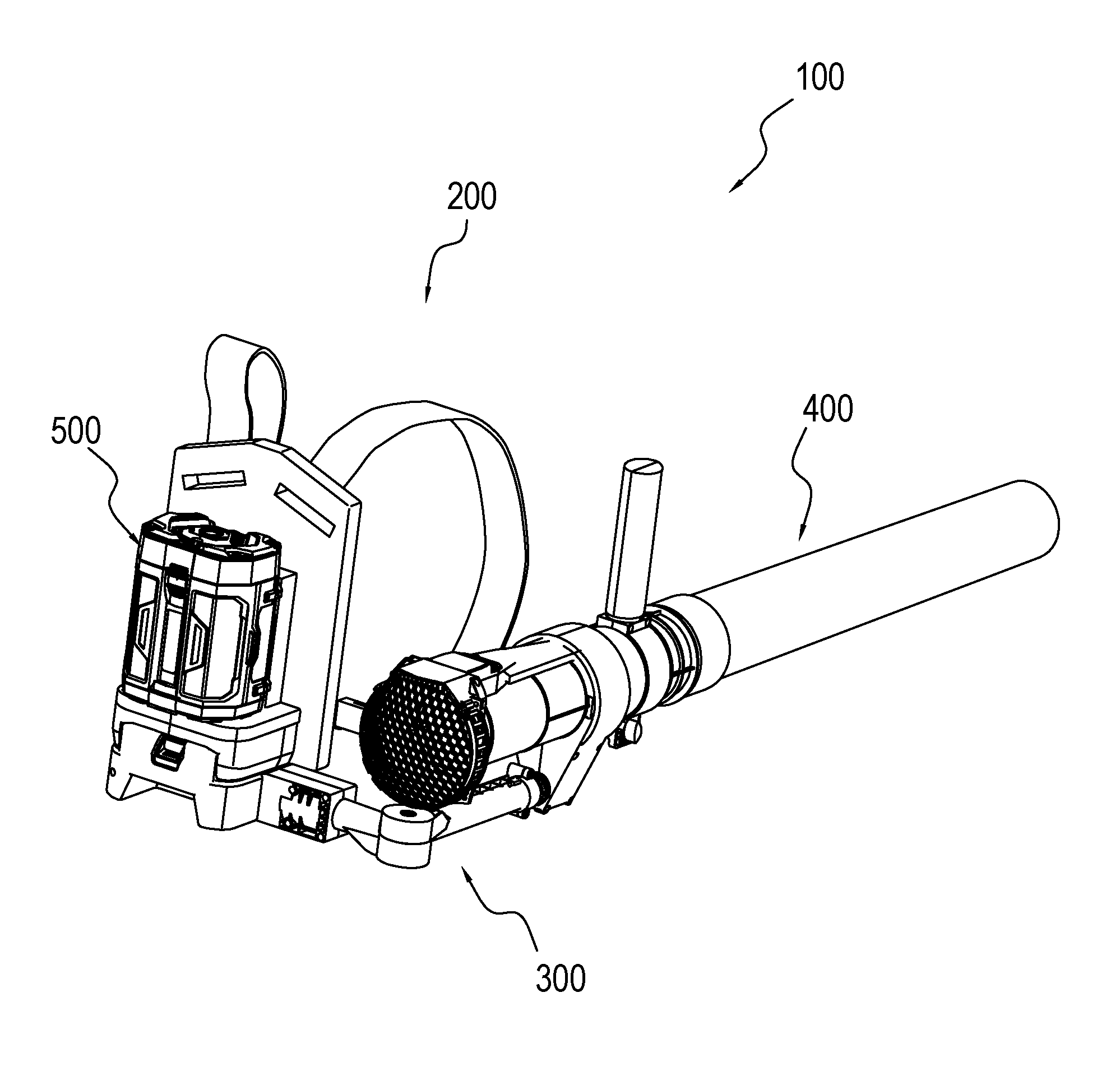
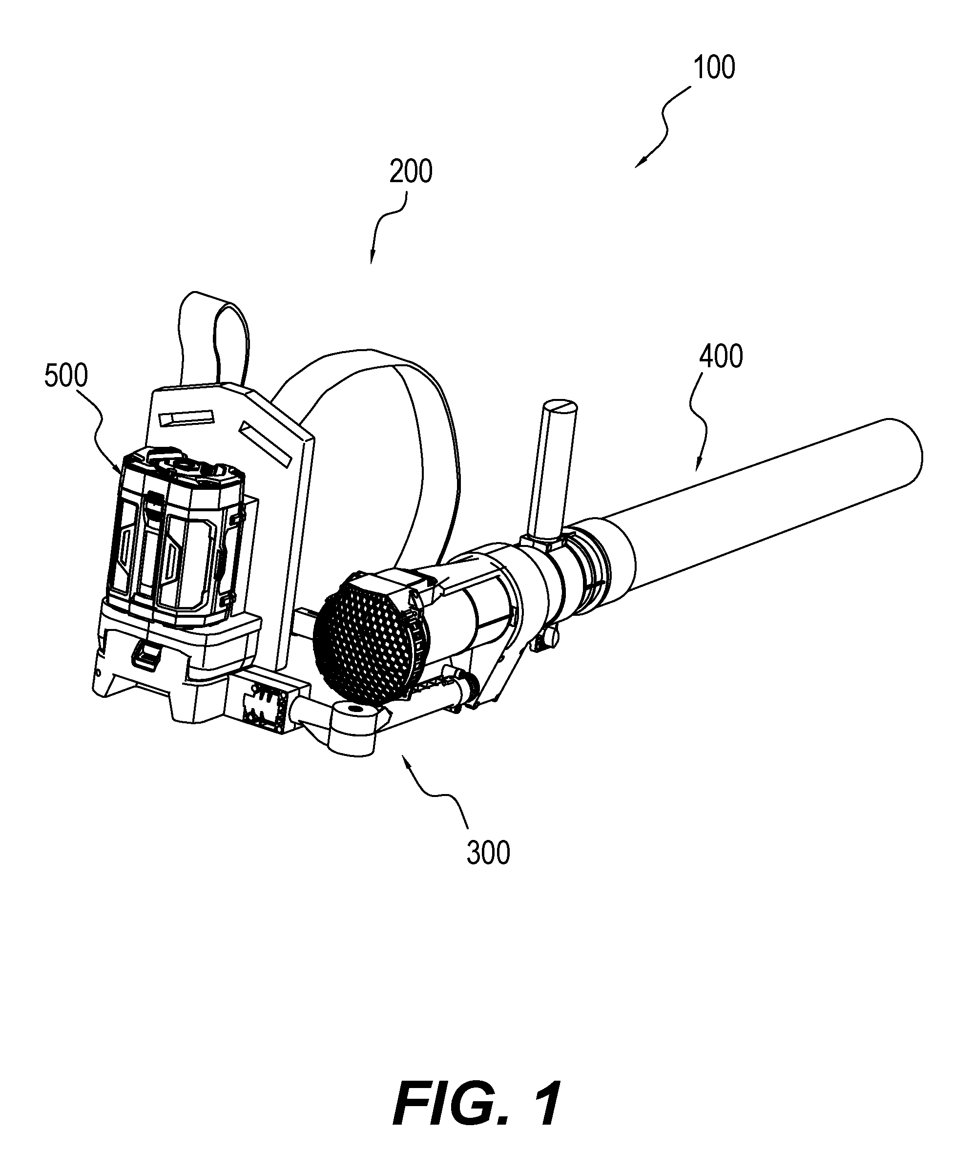
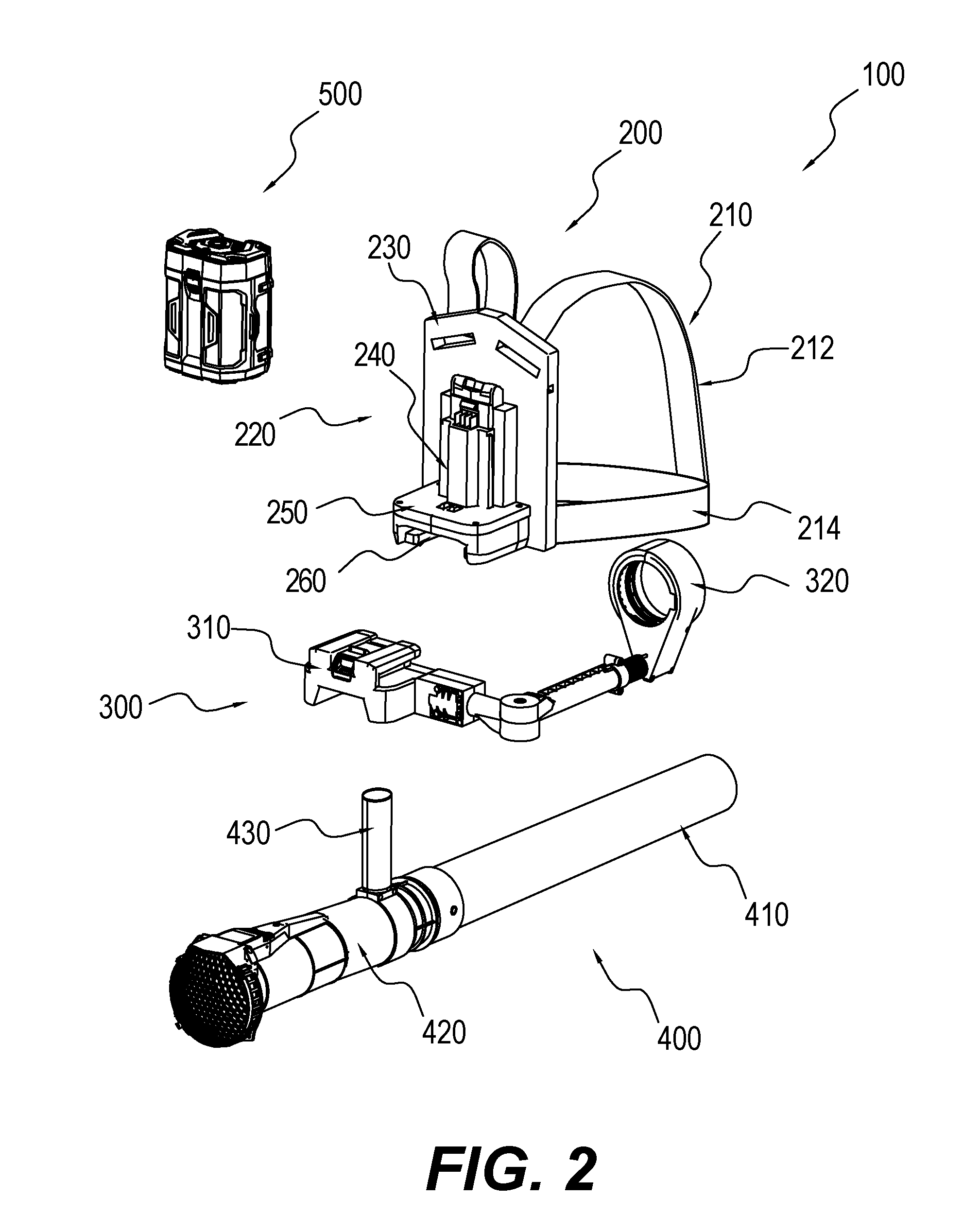
[0007]In one aspect, the present disclosure is directed to a back-mounted power tool system. The back-mounted power tool system may include a battery package that can be used on other power tool systems, a backpack apparatus, a power tool, and a connecting member. The backpack apparatus may include a backpack harness to mount the backpack apparatus onto a user's body and a first connector to removably couple the battery package to the backpack apparatus. The power tool may include a motor driven by a power supply from the battery package. The connecting member may transfer a weight of the power tool and / or a force received from the power tool to the backpack apparatus by rotatably coupling the power tool to the backpack apparatus. The connecting member may further enable the power tool to rotate about a first rotation axis or a second rotation axis, the first rotation axis being perpendicular to the second rotation axis.

Problems solved by technology

The power tool systems that use fossil fuels typically have a combustion engine that can generate undesirable smells, emissions, noise, and / or vibration.
Some power tool systems have the combustion engine designed to be mountable on the back of a user to increase convenience, but the weight of the combustion engine of such power tool systems make the user tire easily over time.
If the voltage of the battery is low, the power supplied to the power tool system may not be enough to operate the power tool, or may result in limited amount of operation time.
But a trade-off for increased power is increased weight.
Increasing the number of battery cells may increase the overall weight and size of the battery and / or the power tool system, which may increase inconvenience, fatigue, and amount of work for the user to operate the power tool system, particularly over long periods of time.
The increased weight and size of the battery and / or the power tool system may also reduce the flexibility for operating the power tool system, and may render the power tool system not suitable for use over long periods of time.
Additionally, conventional battery-powered tool systems have one or more disadvantages that may affect the applications of these systems.
In some situations, the battery of such battery-powered tool system cannot be replaced.
In other situations, the battery forms part of the system and cannot be modified to add or reduce battery cells, or the battery is specially made for a particular type of power tools and cannot be used for other power tools.
These advantages may limit the life of the system, affect the flexibility and convenience for operating the power tool, and limit the application of the system to particular applications, e.g., one or limited number of specific power tools.

Method used


Image

  • Back-mounted power tool systems and methods of use
  • Back-mounted power tool systems and methods of use
  • Back-mounted power tool systems and methods of use

Examples


Embodiment Construction

[0072]This description and the accompanying drawings that illustrate exemplary embodiments should not be taken as limiting. Various mechanical, compositional, structural, chemical, electrical, and operational changes may be made without departing from the scope of this description and the claims, including equivalents. In some instances, well-known structures and techniques have not been shown or described in detail so as not to obscure the disclosure. Similar reference numbers in two or more figures represent the same or similar elements. Furthermore, elements and their associated features that are disclosed in detail with reference to one embodiment may, whenever practical, be included in other embodiments in which they are not specifically shown or described. For example, if an element is described in detail with reference to one embodiment and is not described with reference to a second embodiment, the element may nevertheless be claimed as included in the second embodiment.

[007...


PUM


Abstract

Embodiments of the disclosure are directed to a back-mounted power tool system. The power tool system includes a battery package that can be used on other power tool systems, a backpack apparatus, a power tool, and a connecting member. The backpack apparatus includes a backpack harness to mount the backpack apparatus onto a user's body and a first connector to removably couple the battery package to the backpack apparatus. The power tool includes a motor driven by a power supply from the battery package. The connecting member transfers a weight of the power tool and/or a force received from the power tool to the backpack apparatus by rotatably coupling the power tool to the backpack apparatus. The connecting member further enables the power tool to rotate about a first rotation axis or a second rotation axis, the first rotation axis being perpendicular to the second rotation axis.

Description

CROSS-REFERENCE TO RELATED APPLICATIONS[0001]The present application is based upon and claims priority to Chinese Patent Application No. 201510272609.9 filed May 25, 2015, Chinese Patent Application No. 201510272506.2 filed May 25, 2015, Chinese Patent Application No. 201510287347.3 filed May 29, 2015, Chinese Patent Application No. 201510623933.0 filed Sep. 25, 2015, Chinese Patent Application No. 201510621441.8 filed Sep. 25, 2015, Chinese Patent Application No. 201510624884.2 filed Sep. 25, 2015, and Chinese Patent Application No. 201610070425.9 filed Feb. 1, 2016. The contents of the above-referenced applications are herein incorporated by reference in their entirety.TECHNICAL FIELD[0002]The present disclosure relates to power tool systems in general, and more particularly, to back-mounted power tool systems.BACKGROUND[0003]Power tool systems, such as garden machines, typically include a motor or an engine powered by electricity or fossil fuels. The power tool systems that use f...

Claims


Application Information

Patent Timeline
Patent Type & Authority Applications(United States)
IPC IPC(8): A45F3/14A47L5/14B25F5/02
CPCA45F3/14A45F2003/146A47L5/14B25F5/02A01G3/053A01G20/47E01H1/0809
Inventor YAMAOKA, TOSHINARINIE, FANGJIEGUO, JIANPENG
Owner CHERVON HK LTD WANCHAI
Why Eureka
Try Eureka