Articulated chain with expansion-type outer link plate

a technology of expansion-type outer link plate and articulation chain, which is applied in the direction of driving chain, belt/chain/gearing, belt/chain/gearing, etc., can solve the problems of increasing the mounting difficulty, and increasing the manufacturing cost and reject rate. , to achieve the effect of increasing the expandability of the outer link plate, good strength characteristics, and adequate operational reliability

Inactive Publication Date: 2016-12-01
IWIS MOTORSYSTEME GMBH & CO KG
View PDF2 Cites 11 Cited by
  • Summary
  • Abstract
  • Description
  • Claims
  • Application Information

AI Technical Summary

Benefits of technology

[0010]In the case of an articulated chain of the generic kind, the above object is achieved according to the present invention in that the outer link plates exhibit at least one expansion opening between the pin holes. This kind of structural design of the outer chain link plate allows an increased expandability of the outer link plate through the weakening of said outer link plate between the pin holes. This has the effect that, when a load is applied to the articulated chain during operation, the outer link plate will be expanded more strongly, whereas the joint pin will be bent less strongly. Due to the reduced bending of the joint pin, the latter can be in better full-area contact with the articular surfaces of the inner link plates, whereby the resultant surface pressure will be reduced. The reduced surface pressure in the joint opening of the inner chain links leads, in total, to a substantially improved sliding behavior and to reduced wear. Also during mounting of the outer chain links, the increased expandability of the outer chain links allows the skewed position of the joint pins to be reduced or easily compensated for, and thus easier mounting of the outer link plates.
[0011]For accomplishing a good uniform distribution of stress in the outer link plate when the articulated chain operates under load, the expansion opening may be elongate in shape, a longitudinal axis of the expansion opening extending substantially perpendicular to the link-plate longitudinal direction especially in the case of narrow outer link plates.
[0012]According to an advantageous embodiment, the expansion opening has rounded corners and a shape that is convex in the link-plate longitudinal direction. The rounded corners and the convex shape of the expansion opening guarantee that the stress can distribute as freely as possible in the outer link plate around the expansion opening. For an optimum structural design of the expansion opening with respect to the distribution of stress in the outer link plate as well as with respect to mass reduction of the articulated chain, the maximum height of the expansion opening may be between 10% and 50%, preferably between 20% and 40%, of the maximum width of the outer link plate. The width of the expansion opening may be between 70% and 110% of the maximum height of the expansion opening. The convex shape of the expansion opening in the link-plate longitudinal direction may have a radius of 0.2 to 0.4 of the pitch of the outer link plate.

Problems solved by technology

This skewed position makes it much more difficult to mount the second outer link plate and increases thus the manufacturing costs and the reject rate.
The use of hardened joint pins, which is common practice in the case of modern link chains, increases the mounting problems caused by a skewed position of the joint pins relative to one another.
It is true that these difficulties can be reduced through smaller tolerances for the spacing of the link plate openings, but, due to the normally used method of manufacturing chain link plates by means of punching and shaving, such optimizations are only possible to a very limited extent and cause high tool costs.
Unfortunately, the increased amount of tolerance and the larger diameter of the pin holes of the central link plates allow not only easier mounting of the outer link plates during the manufacturing phase, but they also cause uneven loads on the outer and central link plates of the outer chain link during operation.
In addition to the uneven loads applied to the outer and central link plates, this also results in increased bending of the pin, whereby more wear will occur at the inner link plates as a result of so-called edge bearers.
Due to the bending of the joint pins, the area of the articular surfaces of the inner link plates adjoining the outer link plates will be subject to a higher surface pressure, which causes more wear at the joint pin or at the articular surface of the inner link plates.
Although bending of the joint pins can be reduced in this way, the directed assembly of the outer and central link plates during mounting of the link chains requires a high manufacturing effort.
The various problems of the prior art articulated chains during mounting and operation resulted in different structural designs for solving the problems in question, e.g. the use of hardened chain pins, the reduction of manufacturing tolerances or the variation of press fits, without being able to fully eliminate the respective drawbacks or to avoid new drawbacks.

Method used


Image

  • Articulated chain with expansion-type outer link plate
  • Articulated chain with expansion-type outer link plate
  • Articulated chain with expansion-type outer link plate

Examples


Embodiment Construction

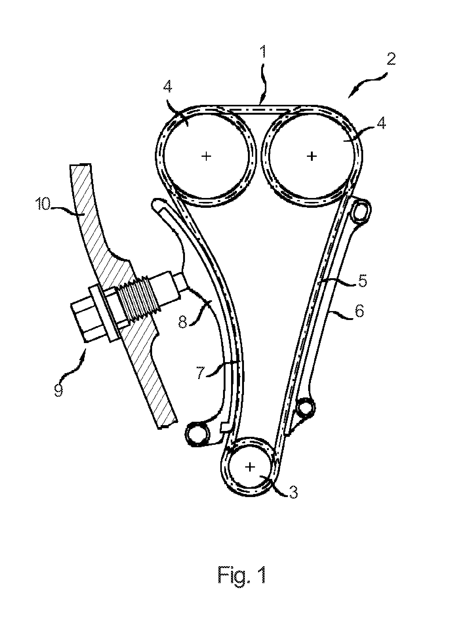
[0030]FIG. 1 shows the use of an articulated chain according to the present invention, e.g. of a plate link chain 1 in a chain drive 2 of an internal combustion engine. This chain drive 2 may be a timing chain drive of an internal combustion engine, comprising a lower crankshaft sprocket 3 and two upper juxtaposed camshaft sprockets 4. The link chain 1 is flexibly wrapped around the camshaft sprockets 4 and the crankshaft sprocket 3 and connects them to one another. In the tight span 5 of the chain drive 2 a guide rail 6 is arranged, along which the link chain 1 slides. The oppositely disposed slack span 7 of the chain drive 2 has provided thereon a tensioning rail 8, which is pivotably supported in the vicinity of the crankshaft sprocket 3 and which is adapted to be pressed against the link chain 1 by means of a tensioning device 9 so as to provide a pretension to the slack span 7 of the chain drive 2. In the present embodiment according to FIG. 1, the tensioning device 9 is config...


PUM


Abstract

An articulated chain includes alternate outer chain links and inner chain links interconnected by respective chain joints. The outer chain links comprise two outer link plates that are spaced apart in parallel, the outer link plates having two pin holes, which are spaced apart in the link-plate longitudinal direction and which each have fixedly arranged therein a respective joint pin of the chain joints. The inner chain links comprise two inner link plates that are spaced apart in parallel, and the joint pin being pivotably arranged in a joint opening of the inner chain links. The outer link plates comprise at least one expansion opening between the pin holes in order to reduce the bending of the joint pin and the surface pressure in the joint opening of the inner chain links, so as to improve the sliding behavior and the wear properties of the chain joints.

Description

CROSS-REFERENCE TO RELATED APPLICATION[0001]This application claims priority to foreign German patent application No. DE 202015003932.4, filed on May 29, 2015, the disclosure of which is incorporated by reference in its entirety.FIELD OF THE INVENTION[0002]The present invention relates to an articulated chain with alternate outer chain links and inner chain links interconnected by respective chain joints, said outer chain links comprising two outer link plates that are spaced apart in parallel, said outer link plates having two pin holes, which are spaced apart in the link-plate longitudinal direction and which each have fixedly arranged therein a respective joint pin of the chain joints, said inner chain links comprising two inner link plates that are spaced apart in parallel, and said joint pin being pivotably arranged in a joint opening of the inner chain links.BACKGROUND[0003]Articulated chains with inner chain links comprising two inner link plates and two joint bushings, posit...

Claims


Application Information

Patent Timeline
Patent Type & Authority Applications(United States)
IPC IPC(8): F16G13/06F16H7/06F16H7/08F16G13/04
CPCF16G13/06F16H7/08F16H7/06F16G13/04F16G13/08
Inventor RITZ, ANDREASFELD, ERWINELWAN, KARIM
Owner IWIS MOTORSYSTEME GMBH & CO KG
Why Eureka
Try Eureka