Narrow bezel display device

a display device and narrow bezel technology, applied in static indicating devices, instruments, non-linear optics, etc., can solve the problems of weak adhesiveness of the sealant, easy damage of circuit units which overlap the sealant, and easy damage of the circuit unit which overlaps the sealant, so as to reduce the width of the bezel, improve the adhesiveness, and reduce the bonding problem

Active Publication Date: 2016-12-01
LG DISPLAY CO LTD
View PDF5 Cites 31 Cited by
  • Summary
  • Abstract
  • Description
  • Claims
  • Application Information

AI Technical Summary

Benefits of technology

[0012]In order to solve the above-described problems and other limitations associated with the related art, an object of the present disclosure is to provide a display device in which a sealant has improved adhesiveness in a region where t

Problems solved by technology

However, some areas of a circuit in the non-display area may be formed of a material whose adhesiveness to the sealant is not strong.
Therefore, even though the sealant extends to the circuit portion, the bonding problem between the upper substrate and the lower substrate may be caused due to weak adhesiveness.
Further, the circuit unit which overlaps the sealant may be easily damaged by an external force applied to the panel.
In this case, a foreign material permeates through the damaged portion to cause problems such as electro-chemical corrosion/corrosion of me

Method used


Image

  • Narrow bezel display device
  • Narrow bezel display device
  • Narrow bezel display device

Examples


Embodiment Construction

[0024]Hereinafter, exemplary embodiments of the present disclosure will be described in detail with reference to the drawings.

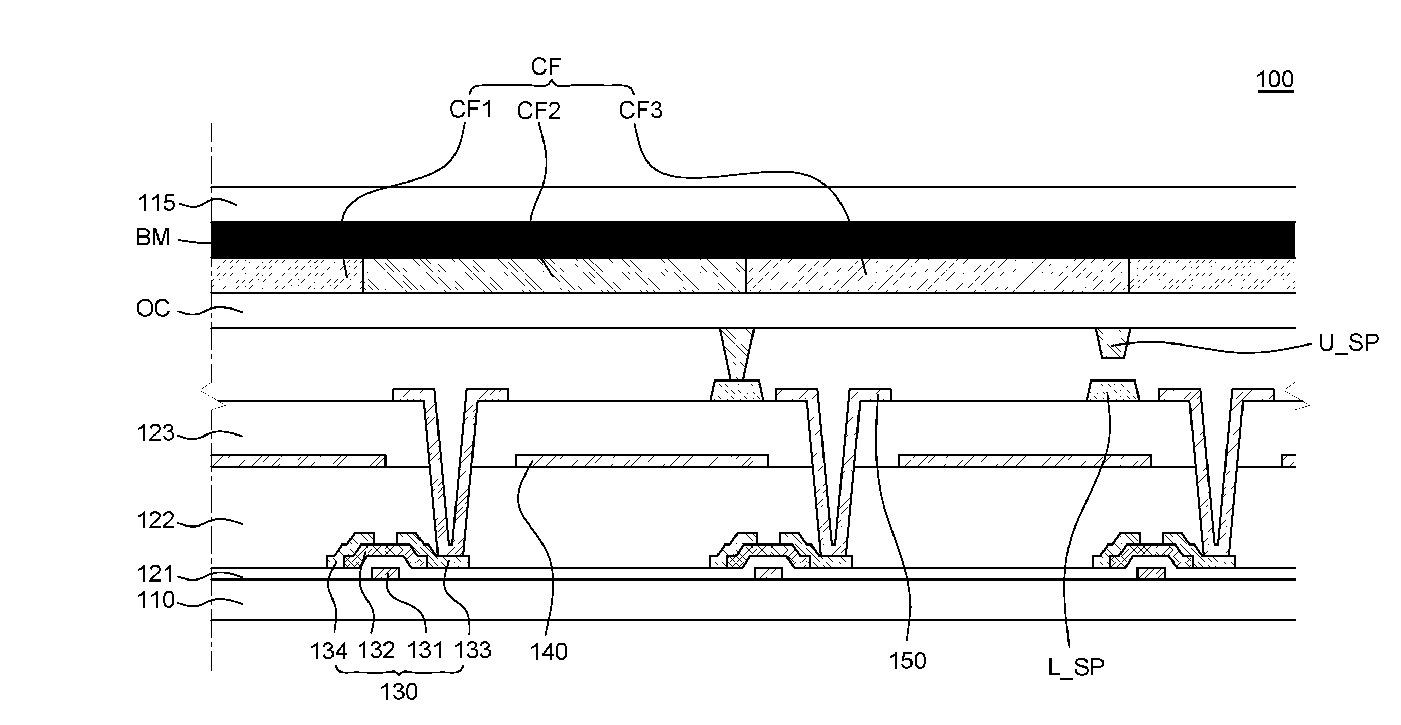
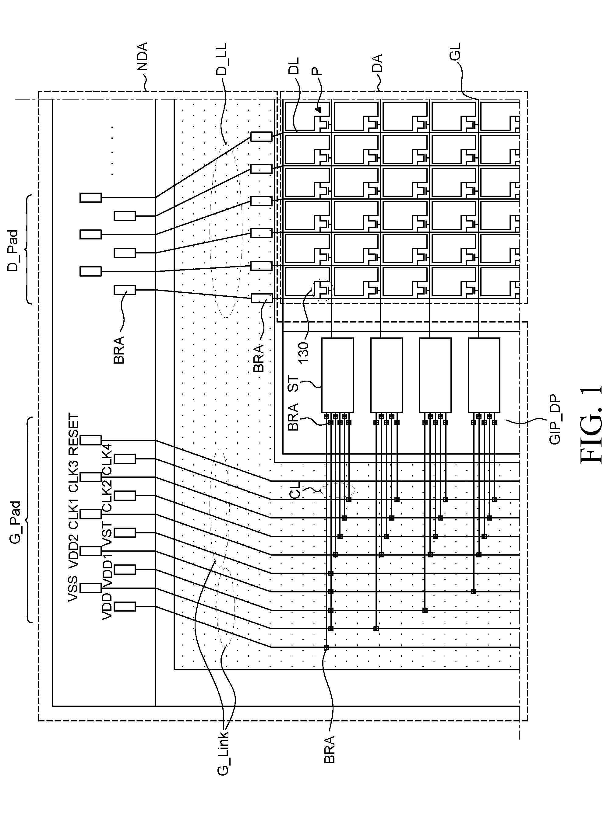
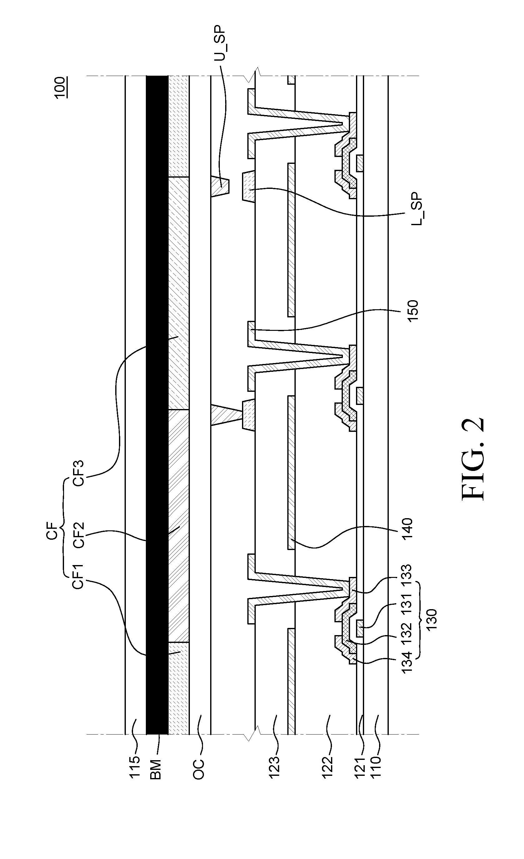
[0025]FIG. 1 is a schematic plane view of a display device according to an exemplary embodiment of the present disclosure and FIG. 2 is a schematic cross-sectional view of a pixel located in a display area of a display device according to an exemplary embodiment of the present disclosure. All the components of the display device according to all embodiments of the present disclosure are operatively coupled and configured.

[0026]A display device includes a display panel 100 including a plurality of pixels P which outputs light. When the display panel 100 is embodied as a liquid crystal panel, the display panel 100 is configured by a structure in which liquid crystal LC is filled between a first substrate 110 (an upper substrate or a lower substrate) and a second substrate 115 (an upper substrate or a lower substrate). The first substrate 110 and the second subs...


PUM


Abstract

A display device according to an embodiment includes a lower substrate in which a display area and a non-display area are divided and an upper substrate which corresponds to the lower substrate and includes a black matrix BM. Further, the display device can include a bezel which is located on the non-display area and includes a GIP driver, a plurality of signal transmission lines, a connection line connecting the GIP driver and the plurality of signal transmission lines, and a seal area equipped with a sealant, in a direction being apart from one side of the display area, a plurality of bridge patterns which is located on the non-display area and electrically connects the GIP driver and the connection line, and the connection line and the plurality of signal transmission lines, respectively, and a plurality of shield patterns enclosing the plurality of bridge patterns. Also, the display device can include a plurality of shield patterns which minimize an area in which the sealant and the plurality of bridge patterns are in directly contact with each other.

Description

CROSS-REFERENCE TO RELATED APPLICATIONS[0001]This application claims the priority of Korean Patent Application No. 10-2015-0076972 filed on May 31, 2015 and Korean Patent Application No. 10-2016-0059666 filed on May 16, 2016, in the Korean Intellectual Property Office, the disclosures of all these applications are incorporated herein by reference.BACKGROUND[0002]Field of the Invention[0003]The present disclosure relates to a display device. More particularly, the present disclosure relates to a display device which can reduce a bezel width by disposing a sealant which bonds an upper substrate and a lower substrate, to extend to a signal line portion or a gate in panel (GIP) driver.[0004]Description of the Related Art[0005]As a display device, there are a liquid crystal display device and an organic electroluminescence display device configured to include an upper substrate, a lower substrate, where a liquid crystal layer or an organic light emitting device formed between two substra...

Claims


Application Information

Patent Timeline
IPC IPC(8): G02F1/1345G02F1/1343G02F1/1339G02F1/133H01L51/52H01L27/32
CPCG02F1/13452G02F2001/13398H01L51/5237H01L51/5246H01L27/3272H01L27/3276H01L27/3262H01L27/3246G02F1/13394G02F1/13306G02F1/1339G02F1/13439H01L27/124H01L2251/308H01L51/5284G02F1/1345G02F2201/50G02F1/13398H10K59/122H10K59/131H10K50/8426H10K50/865H10K59/1201
Inventor KIM, SANGWOONYU, SANGHEECHO, SUNGHYUNLEE, SANGGUL
Owner LG DISPLAY CO LTD
Why Eureka
Try Eureka