Automatic driving system for vehicle

a technology of automatic driving and driving system, which is applied in the direction of vehicle position/course/altitude control, process and machine control, instruments, etc., can solve the problems of not being able to reduce fuel consumption during automatic driving, and achieve the effect of reducing fuel consumption, reducing fuel consumption, and reducing fuel consumption

Inactive Publication Date: 2016-12-01
TOYOTA JIDOSHA KK
View PDF3 Cites 46 Cited by
  • Summary
  • Abstract
  • Description
  • Claims
  • Application Information

AI Technical Summary

Benefits of technology

[0007]However, JP 2008-129804 A does not specifically describe how fuel consumption is reduced during automatic driving. Therefore, it is not clear how to reduce fuel consumption during automatic driving. The invention provides an automatic driving system for a vehicle, which shows a specific technique for reducing fuel consumption during automatic driving.
[0008]An aspect of the invention provides an automatic driving system for a vehicle. The automatic driving system includes an external sensor and an electronic control unit. The external sensor detects vehicle peripheral information. The electronic control unit is configured to generate a vehicle travel plan along a preset target route on a basis of map information and the vehicle peripheral information detected by the external sensor. The electronic control unit is configured to control automatic driving of the vehicle on a basis of the vehicle travel plan. The electronic control unit is configured to estimate whether the vehicle peripheral information detected by the external sensor allows the vehicle to keep a vehicle target speed set on a basis of the vehicle travel plan or temporarily does not allow the vehicle to keep the vehicle target speed. The electronic control unit is configured to, when it is estimated that the vehicle peripheral information temporarily does not allow the vehicle to keep the vehicle target speed, generate a plurality of vehicle travel plans during a travel duration for which it is estimated that the vehicle peripheral information temporarily does not allow the vehicle to keep the vehicle target speed, and select one of the plurality of vehicle travel plans, which provides a lowest fuel consumption of an engine. The electronic control unit is configured to, during the travel duration for which it is estimated that the vehicle peripheral information temporarily does not allow the vehicle to keep the vehicle target speed, control driving of the engine and driving of a steering apparatus in accordance with the selected one of the vehicle travel plans.
[0009]With the automatic driving system according to the above aspect, when it is estimated that the vehicle peripheral information temporarily does not allow the vehicle to keep the vehicle target speed, the vehicle travel plan that provides the lowest fuel consumption is generated, and it is possible to appropriately reduce fuel consumption by causing the vehicle to travel on the basis of the generated vehicle travel plan. In the automatic driving system according to the above aspect, the electronic control unit may be configured to, when the host vehicle is not allowed to travel at the vehicle target speed due to another vehicle ahead of the host vehicle in a traveling direction of the host vehicle, estimate that the vehicle peripheral information temporarily does not allow the host vehicle to keep the vehicle target speed set on the basis of the vehicle travel plan. In the automatic driving system according to the above aspect, the electronic control unit may be configured to, when a host vehicle is not allowed to travel at the vehicle target speed due to the other vehicle ahead of the host vehicle in the traveling direction of the host vehicle and when a distance between the host vehicle and the other vehicle ahead of the host vehicle in the traveling direction of the host vehicle is shorter than or equal to a predetermined distance, estimate that the vehicle peripheral information temporarily does not allow the host vehicle to keep the vehicle target speed set on a basis of

Problems solved by technology

Therefore, it is not clear how to reduce

Method used


Image

  • Automatic driving system for vehicle
  • Automatic driving system for vehicle
  • Automatic driving system for vehicle

Examples


Embodiment Construction

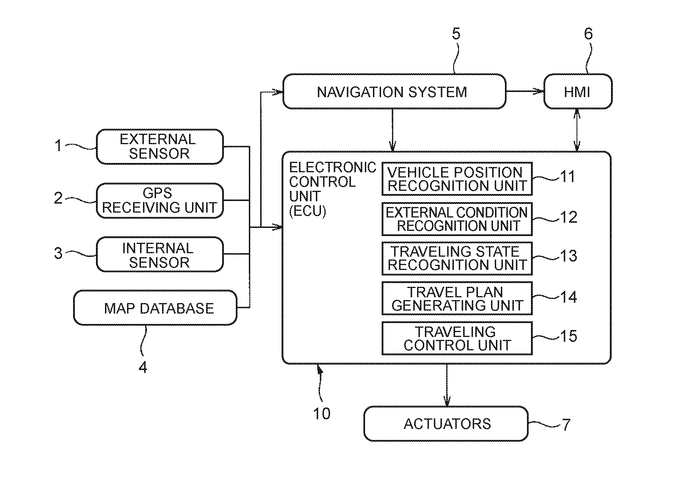
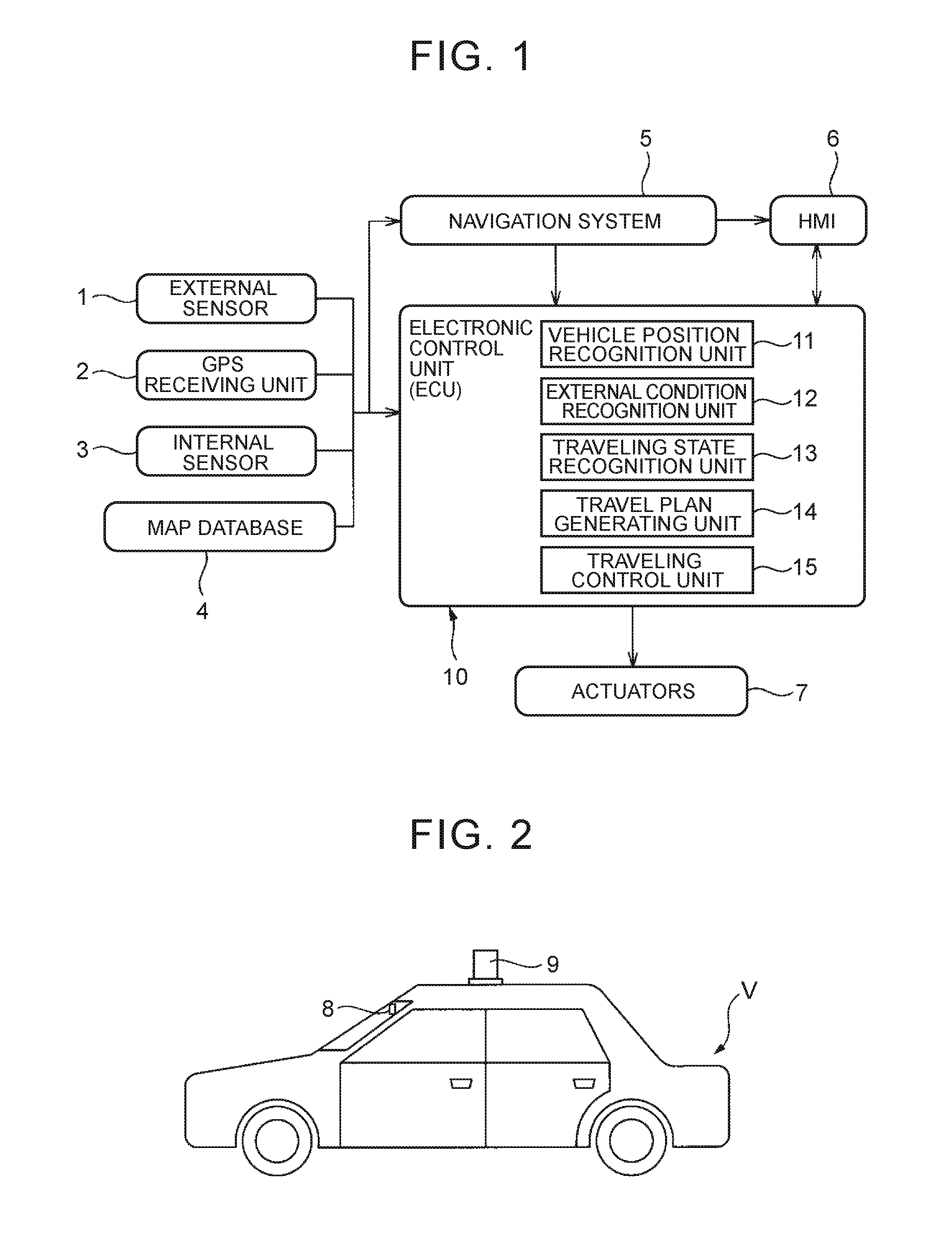
[0037]FIG. 1 is a block diagram that shows the configuration of an automatic driving system for a vehicle, which is mounted on a vehicle, such as an automobile. As shown in FIG. 1, the automatic driving system for a vehicle includes an external sensor 1, a global positioning system (GPS) receiving unit 2, an internal sensor 3, a map database 4, a navigation system 5, a human machine interface (HMI) 6, various actuators 7, and an electronic control unit (ECU) 10. The external sensor 1 detects vehicle peripheral information.

[0038]In FIG. 1, the external sensor 1 is a detection device for detecting an external condition that is peripheral information around the vehicle V. The external sensor 1 includes at least one of a camera, a radar and a laser imaging detection and ranging (LIDAR). For example, as denoted by reference numeral 8 in FIG. 2, the camera is provided on the back side of a windshield of the vehicle V. The camera 8 captures an image ahead of the vehicle V. Information capt...


PUM


Abstract

An automatic driving system for a vehicle includes an external sensor and an electronic control unit. The electronic control unit is configured to estimate whether the vehicle peripheral information detected by the external sensor allows the vehicle to keep a vehicle target speed set on the basis of a vehicle travel plan or temporarily does not allow the vehicle to keep the vehicle target speed. The electronic control unit is configured to, when it is estimated that the vehicle peripheral information temporarily does not allow the vehicle to keep the vehicle target speed, generate a plurality of vehicle travel plans during a travel duration for which it is estimated that the vehicle peripheral information temporarily does not allow the vehicle to keep the vehicle target speed, and select one of the plurality of vehicle travel plans, which provides a lowest fuel consumption of an engine.

Description

INCORPORATION BY REFERENCE[0001]The disclosure of Japanese Patent Application No. 2015-105555 filed on May 25, 2015 including the specification, drawings and abstract is incorporated herein by reference in its entirety.BACKGROUND OF THE INVENTION[0002]1. Field of the Invention[0003]The invention relates to an automatic driving system for a vehicle.[0004]2. Description of Related Art[0005]There is known an automatic driving system for a vehicle (see, for example, Japanese Patent Application Publication No. 2008-129804 (JP 2008-129804 A).[0006]The automatic driving system includes an external sensor for detecting vehicle peripheral information. The automatic driving system generates a vehicle travel plan along a preset target route on the basis of map information and the vehicle peripheral information detected by the external sensor, and controls automatic driving of the vehicle on the basis of the generated vehicle travel plan. With this automatic driving system, the vehicle travel p...

Claims


Application Information

Patent Timeline
IPC IPC(8): G05D1/00G01S19/13G05D1/02G01C21/36
CPCG05D1/0088G01C21/36G01S19/13G05D2201/0213G05D1/0248G05D1/0223G05D1/0257B60W10/06B60W10/20B60W30/12B60W30/143B60W40/02B60W40/105B60W50/08B60W2556/50B60W2554/00G05D1/0217G01C21/34B60W50/0097B60W30/18163G01S2013/93273G01S17/931B60K31/0058G08G1/123B60K2310/244B60W2530/13B60W30/00
Inventor SUGIMOTO, KAZUHIRO
Owner TOYOTA JIDOSHA KK
Why Eureka
Try Eureka