Die bonding apparatus comprising an inert gas environment

a gas environment and die bonding technology, applied in electrical devices, semiconductor devices, semiconductor/solid-state device details, etc., can solve problems such as performance degradation of final products, and achieve the effect of avoiding performance degradation of assembled electronic packages and reducing the amount of impurities

Active Publication Date: 2016-12-01
ASMPT SINGAPORE PTE LTD
View PDF31 Cites 4 Cited by
  • Summary
  • Abstract
  • Description
  • Claims
  • Application Information

AI Technical Summary

Benefits of technology

[0005]It is thus an object of this invention to seek to provide a die bonding apparatus which is able to reduce the amount of impurities in order to avoid performance degradation of assembled electronic packages.

Problems solved by technology

Impurities on bonding materials are undesirable because impurities prevent good contact between the bonding materials and bonding surfaces, which may result in performance degradation of final products.

Method used


Image

  • Die bonding apparatus comprising an inert gas environment
  • Die bonding apparatus comprising an inert gas environment
  • Die bonding apparatus comprising an inert gas environment

Examples


Embodiment Construction

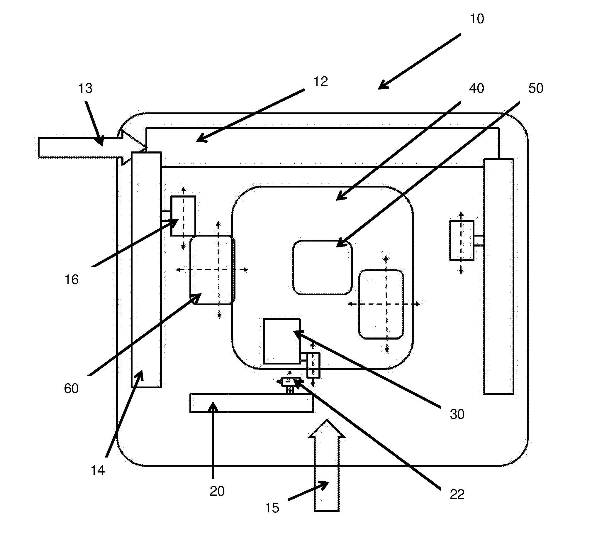
[0017]FIG. 1 is a plan view of a die bonder 10 according to the preferred embodiment of the present invention. The die bonder 10 comprises a transfer system, such as a highway transfer system 12 which is configured to transport a bonding substrate or die package to a location where a substrate transfer arm (STA) head 16 of a substrate transfer arm (STA) 14 is operative to pick up the substrate. The substrate is supplied to the highway transfer system 12 from a substrate supply 13. The STA 14, which is movable in an X axis, is configured to transport the substrate and place it onto a bond stage 60 at a loading position. The bond stage 60, which is movable along X-Y axes, is movable below a first inert gas container or macro inert environment 40. The macro inert environment 40 has a first inert gas concentration. The macro inert environment 40 comprises a second inert gas container or core inert environment 50 which has a second inert gas concentration. The second inert gas concentrat...


PUM


Abstract

A die bonding apparatus comprising a first inert gas container having a first inert gas concentration, and a second inert gas container having a second inert gas concentration enclosed within the first inert gas container. The second inert gas concentration is higher than the first inert gas concentration. The die bonding apparatus further comprises a bond head located in the second inert gas container for receiving a die for bonding, and a third inert gas container having an inert gas environment that is separate from the first and second inert gas containers and where a substrate is locatable for die bonding. The bond head is operative to move the die between a first position within the second inert container and a second position within the third inert gas container to bond the die onto the substrate located in the third inert gas container.

Description

FIELD OF THE INVENTION[0001]The invention relates to a die bonding apparatus, and in particular to a die bonding apparatus comprising an inert gas environment to conduct die bonding.BACKGROUND[0002]Assembly of an integrated circuit (IC) when manufacturing an electronic package involves attaching a die or chip to a substrate. One example of a bonding process is the thermal compression bonding (TCB) process, which may be used for flip-chip bonding. The TCB process is not a batch process, unlike a conventional oven reflow process. The bonding of a flip-chip die during a TCB process is performed one die at a time. The die from the silicon wafer is flipped and transferred to a bond-arm with bumps on the die facing down. The die carried by the bond-arm is then placed onto a bonding location of the substrate or onto another die. A small compressive force is applied onto the die to press it against the substrate or the other die to ensure good contact between the die and the substrate or be...

Claims


Application Information

Patent Timeline
Patent Type & Authority Applications(United States)
IPC IPC(8): H01L23/00H01L21/677
CPCH01L24/75H01L21/67742H01L2224/75101H01L2224/759H01L2224/75841H01L2224/7565H01L2224/75821H01L21/67144H01L2224/81011H01L2224/75824H01L2224/75305H01L2224/751H01L24/81H01L2224/75251H01L2224/75252H01L2224/75804H01L2224/81024H01L2224/81075H01L2224/81203H01L2224/81093H01L2224/7501H01L2224/81022H01L2924/00012H01L21/185H01L21/52H01L21/54H01L21/67005H01L21/677H01L23/12
Inventor LAU, SIU WINGHUNG, KIN YIKAU, YUK CHEUNGLAI, WING CHIULEE, LEO MANGO, SAI YUEN
Owner ASMPT SINGAPORE PTE LTD
Why Eureka
Try Eureka