Connection device

a technology of connecting terminals and connecting wires, applied in the direction of coupling device connection, printed circuit aspects, instruments, etc., can solve the problems of insufficient electrical conduction, difficult connection, and inability to obtain reliable pressing force, etc., and achieve the effect of reliable connection of terminals

Inactive Publication Date: 2016-12-01
ALPS ALPINE CO LTD
View PDF0 Cites 11 Cited by
  • Summary
  • Abstract
  • Description
  • Claims
  • Application Information

AI Technical Summary

Benefits of technology

[0007]The present invention provides a connection device that can reliably connect terminals provided on two curved flexible substrates.
[0016]The connection device of the present invention is particularly effective when the plurality of first terminals and the plurality of second terminals are connected with anisotropic conductive adhesive. The plurality of first terminals and the plurality of second terminals are accurately opposed to each other, and sufficient pressing force can be applied to the anisotropic conductive adhesive and reliable electrical conduction can be obtained.

Problems solved by technology

However, when connecting a flexible wiring substrate along a curved surface of a flexible substrate, the pitch of terminals on the flexible substrate and the flexible wiring substrate changes compared to that in the flat state according to the curvature, and therefore reliable connection is difficult.
In particular, when connecting terminals using anisotropic conductive adhesive, reliable pressing force cannot be obtained due to terminal pitch mismatch, and sufficient electrical conduction may not be obtained.

Method used


Image

  • Connection device
  • Connection device
  • Connection device

Examples


first embodiment

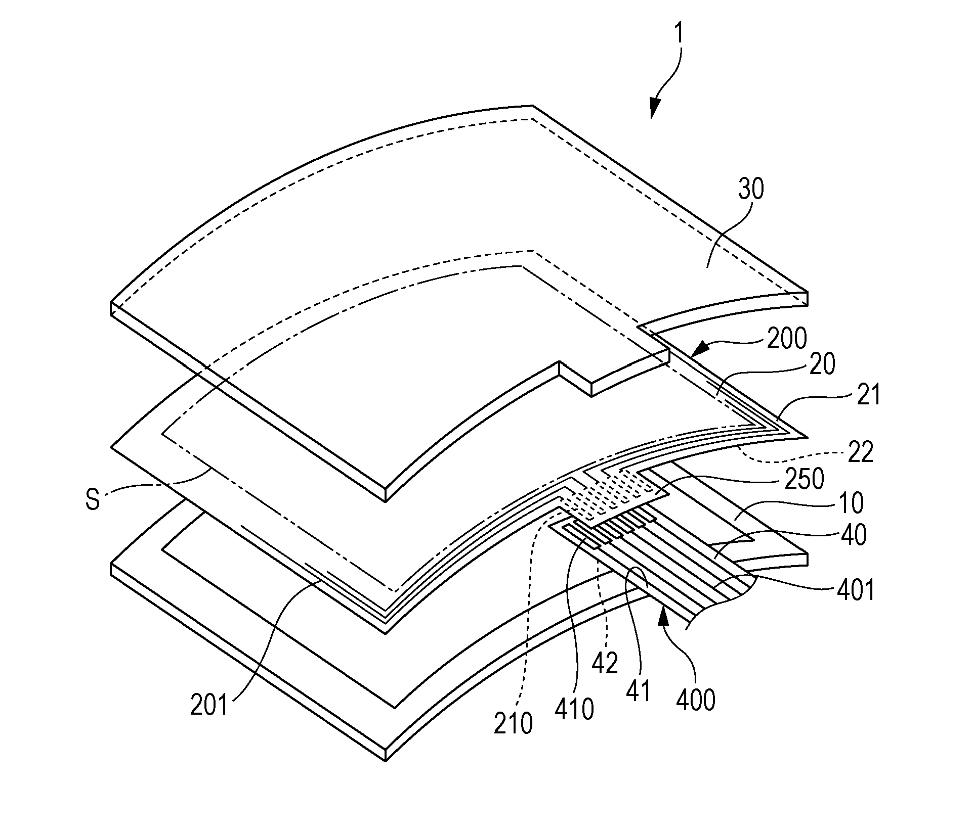
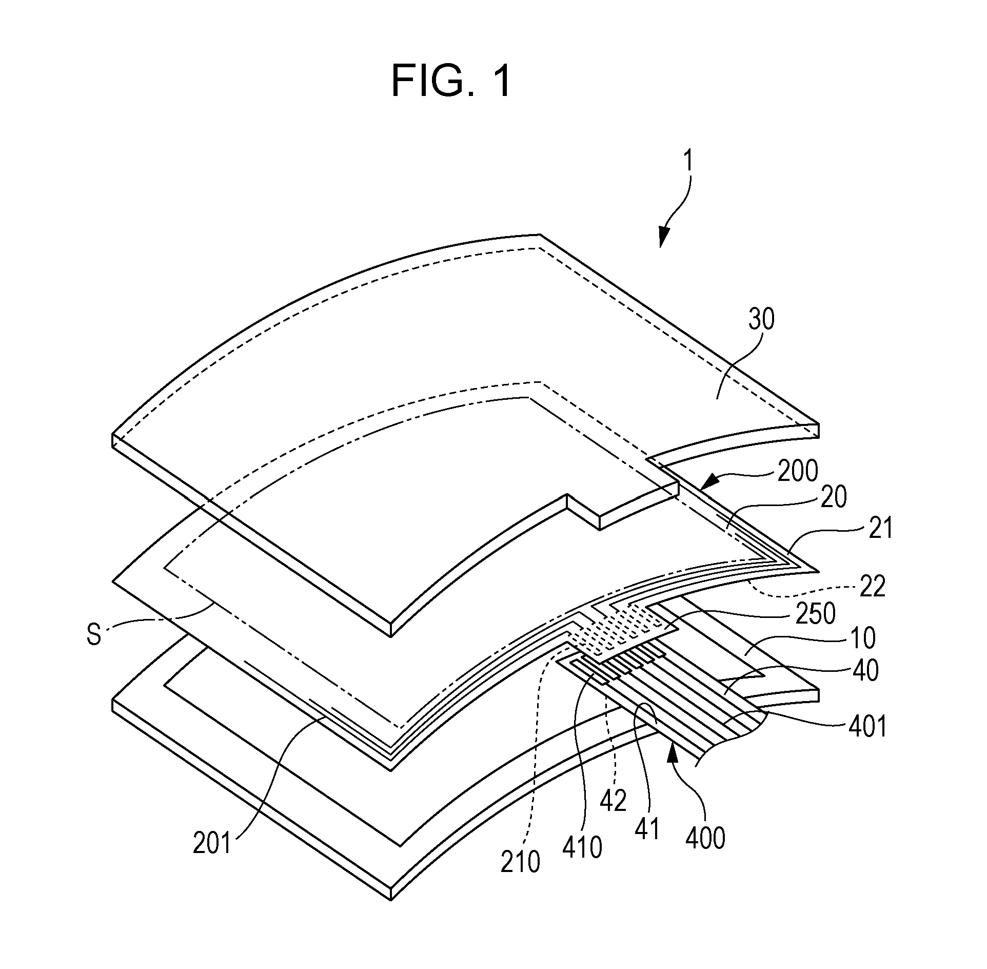
[0024]FIG. 1 shows an exploded perspective view of a touch panel display 1 to which a connection device according to a first embodiment of the present invention is applied.

[0025]The touch panel display 1 shown in FIG. 1 has a display panel 10 using liquid crystal or the like, a touch sensor substrate 20 provided on the top of the display panel 10, and a cover panel 30 provided on the top of the touch sensor substrate 20. The touch panel display 1 shown in FIG. 1 has a curved shape such that the cover panel 30 side is convex.

[0026]To make the curved touch panel display 1, the respective shapes of the display panel 10, the touch sensor substrate 20, and the cover panel 30 are curved. By stacking these, the curved shape of the touch panel display 1 is formed.

[0027]The touch sensor substrate 20 has a light-transmitting first flexible substrate 200 and light-transmitting wiring patterns 201. The wiring patterns 201 are electrically connected to a sensor pattern (not shown) provided throu...

second embodiment

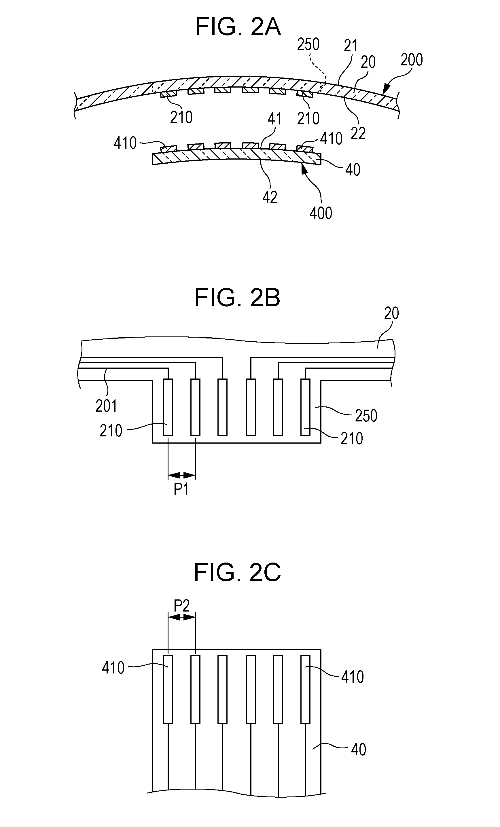
[0051]FIGS. 5A to 5C are schematic sectional views illustrating a connection device according to a second embodiment.

[0052]The connection device according to the second embodiment differs from the connection device according to the first embodiment in the direction of bending. That is, in the second embodiment, the flexible substrates 200 and 400 are curved in the longitudinal direction of the first terminals 210 and the second terminals 410.

[0053]As shown in FIG. 5A, when the flexible substrates 200 and 400 are flat, the length L1′ of the first terminals 210 is set larger than the length L2′ of the second terminals 410. As shown in FIG. 5B, when the flexible substrates 200 and 400 are curved in the longitudinal direction of the first terminals 210 and the second terminals 410, compressive force F2 in the bending direction acts on the concave second surface 22, and tensile force F1 in the bending direction acts on the convex third surface 41. Thereby, the length L1′ of the first ter...


PUM


Abstract

A connection device includes a first flexible substrate having a convex first surface and a concave second surface, a plurality of first terminals provided on the second surface and arranged in the bending direction of the second surface, a second flexible substrate having a convex third surface and a concave fourth surface, and a plurality of second terminals provided on the third surface and arranged in the bending direction of the third surface, and connects the plurality of first terminals and the plurality of second terminals to each other with the second surface and the fourth surface opposed to each other. When the second surface and the third surface are flattened, the pitch of two of the plurality of first terminals is larger than the pitch of two of the plurality of second terminals that are connected to the two first terminals.

Description

CLAIM OF PRIORITY[0001]This application claims benefit of Japanese Patent Application No. 2015-108277 filed on May 28, 2015, which is hereby incorporated by reference.BACKGROUND OF THE INVENTION[0002]1. Field of the Invention[0003]The present invention relates to a connection device that connects terminals provided on two flexible substrates having curved surface shapes.[0004]2. Description of the Related Art[0005]The importance of a touch panel conformed to a curved surface shape is increasing with reduction in thickness of liquid crystal displays and diversification of display forms. Japanese Unexamined Patent Application Publication No. 2013-114672 describes a touch module in which a case and a touch region are curved. Japanese Unexamined Patent Application Publication No. 2012-133428 describes a display device having a liquid crystal panel formed in a curved shape, and a touch panel bonded to a bonding layer on the liquid crystal panel. Japanese Unexamined Patent Application Pub...

Claims


Application Information

Patent Timeline
Patent Type & Authority Applications(United States)
IPC IPC(8): H01R12/78H01R4/04
CPCH01R4/04H01R12/78G06F3/04164H05K1/118H05K1/147H05K1/189H05K3/323H05K2201/094H05K2201/10128G06F3/041G06F2203/04103
Inventor ITO, TAKAYUKI
Owner ALPS ALPINE CO LTD
Why Eureka
Try Eureka