Power converter

a power converter and converter technology, applied in the field of power converters, can solve the problems of complex shielding of power converters, in particular frequency converters, and achieve the effects of improving the electromagnetic compatibility of power converters, high design effort, and compromising performan

Active Publication Date: 2016-12-01
GRUNDFOS HLDG
View PDF4 Cites 11 Cited by
  • Summary
  • Abstract
  • Description
  • Claims
  • Application Information

AI Technical Summary

Benefits of technology

[0008]Against this background, it is an object of the invention to reduce the above-mentioned disadvantages, thus to improve the electromagnetic compatibility of a power converter, in particular of a frequency converter, where possible without compromising the performance and without a high design effort.

Problems solved by technology

The shielding of power converters, in particular of frequency converters, is complex, since a combination of capacitive, magnetic and electromagnetic fields is to be shielded.

Method used


Image

  • Power converter
  • Power converter
  • Power converter

Examples


Embodiment Construction

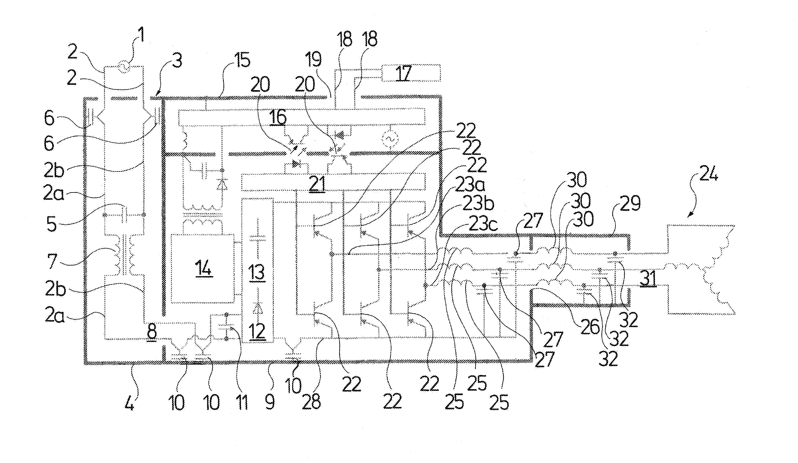
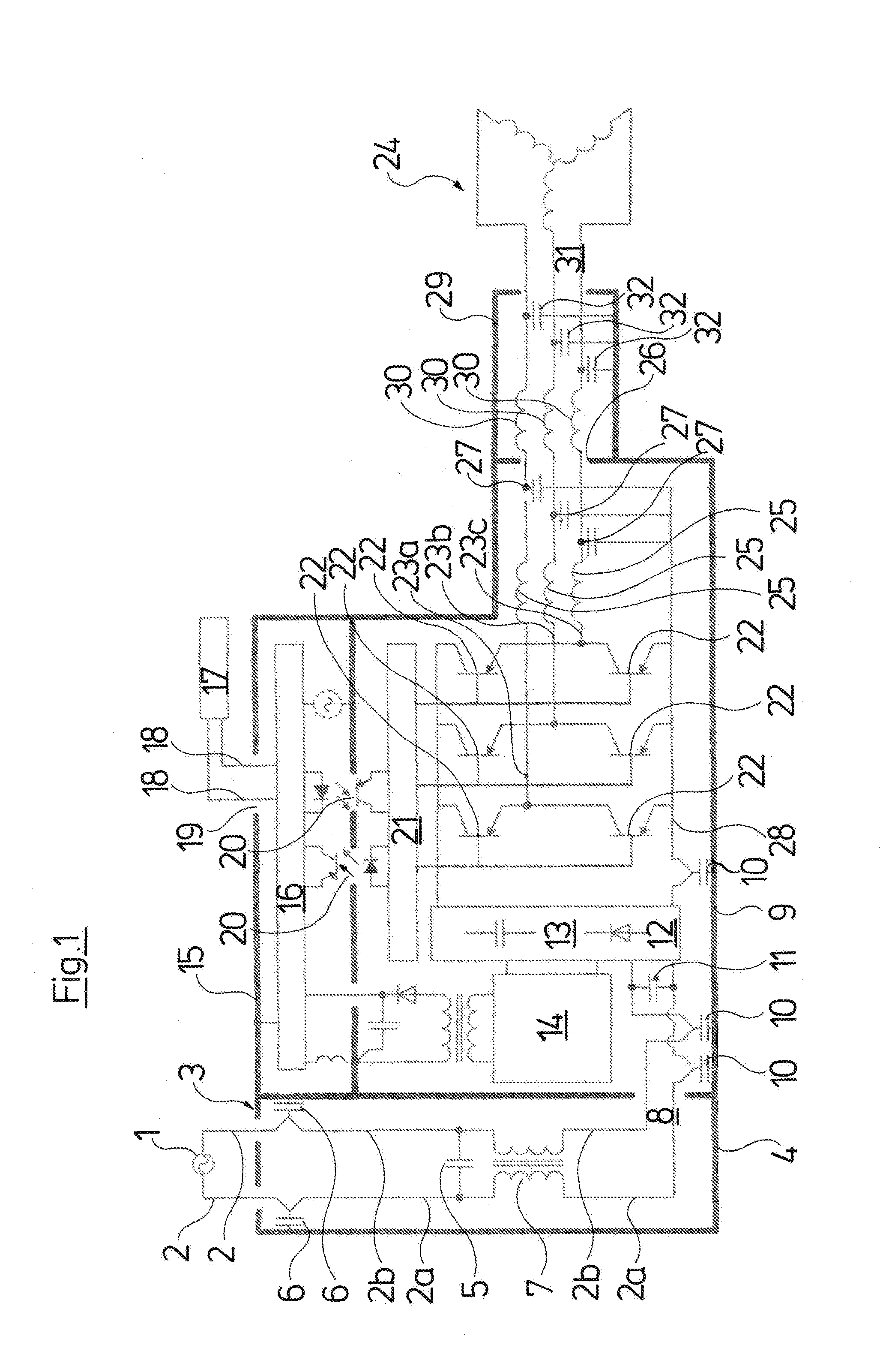
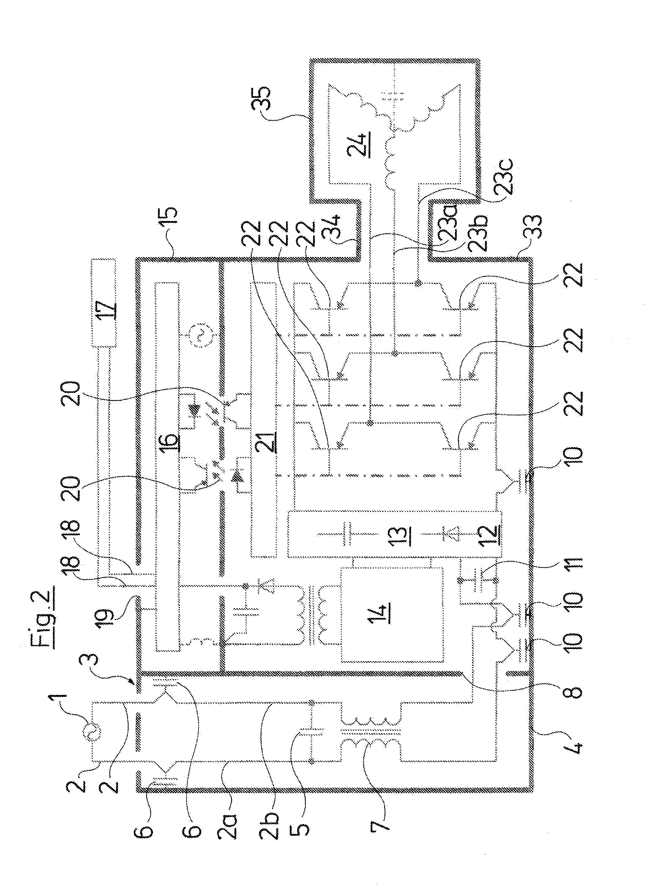
[0039]Referring to the drawings, the frequency converter represented in FIG. 1 is provided for connection current mains 1. The 1 phase version is shown here for simplicity but naturally by adding the necessary wires the same principle can be applied to a multi-phase supply. The supply lead 2 which is to be connected to the alternating current mains 1 is firstly led through an input interference suppression filter 3 which is arranged in a first Faraday cage 4 or is shielded by this. The two conductors 2a and 2b within the input interference suppression filter 3 are connected to one another by way of a capacitor 5, with which it can be the case of an X2 capacitor. The conductors 2a and 2b of the supply lead 2 moreover within the first Faraday cage 4 are conductively connected to the Faraday cage 4 in each case via a capacitor 6.

[0040]Finally, the conductors 2a and 2b, after they have passed the capacitor 5 for the purpose of the short circuit of the high frequencies, are led to a comm...


PUM


Abstract

A frequency converter includes an enclosure, in which electrical and electronic components (5, 6, 7, 22) are arranged and which at least partly is designed as a Faraday cage. At least two Faraday cages (4, 9, 15, 29) are provided within the enclosure, in order to improve the electromagnetic compatibility (EMC).

Description

CROSS REFERENCE TO RELATED APPLICATIONS[0001]This application is a United States National Phase Application of International Application PCT / EP2015 / 051368 filed Jan. 23, 2015 and claims the benefit of priority under 35 U.S.C. §119 of European Patent Application 14153916.3 filed Feb. 5, 2014, the entire contents of which are incorporated herein by reference.FIELD OF THE INVENTION[0002]The invention relates to a power converter, in particular to a frequency converter, with an enclosure, in which electrical and electronic components are arranged and which is at least partly constructed as a Faraday cage.BACKGROUND OF THE INVENTION[0003]Power converters are used nowadays in many technical applications. Thus, for example, with centrifugal pumps which are applied as heating circulation pumps or likewise, it is nowadays counted as belonging to the state of the art, to provide these with a frequency converter which is arranged in a terminal box or frequency converter housing which are mostl...

Claims


Application Information

Patent Timeline
Patent Type & Authority Applications(United States)
IPC IPC(8): H02K11/01H02K11/33H05K9/00H02K5/24H02M5/297H02P27/06
CPCH02K11/01H02M5/297H02K11/33H05K9/0026H02K5/24H02P27/06H02K11/0141H02M7/003H05K9/0037H05K9/00
Inventor WOLF, CHRISTIAN
Owner GRUNDFOS HLDG
Why Eureka
Try Eureka