Apparatus and Methods for Treating Rhinitis

a technology for rhinitis and apparatus, applied in the field of apparatus and methods for ablating tissue regions, can solve the problems of limited effect of medical treatment, acute pain and swelling, overtreatment, bone damage, etc., and achieve the effect of optimal tissue freezing and ablation of posterior nasal nerves

Active Publication Date: 2016-12-08
ARRINEX INC
View PDF2 Cites 17 Cited by
  • Summary
  • Abstract
  • Description
  • Claims
  • Application Information

AI Technical Summary

Benefits of technology

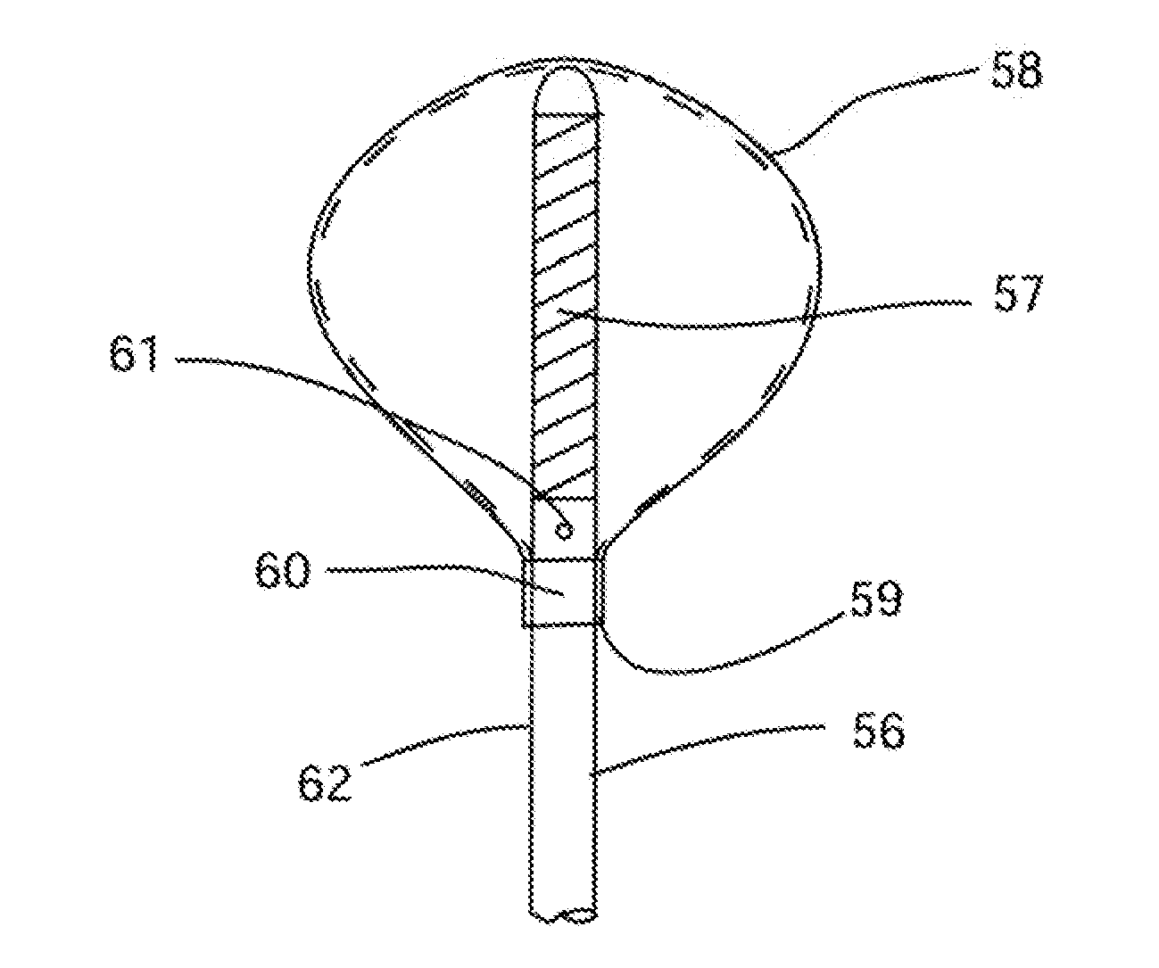
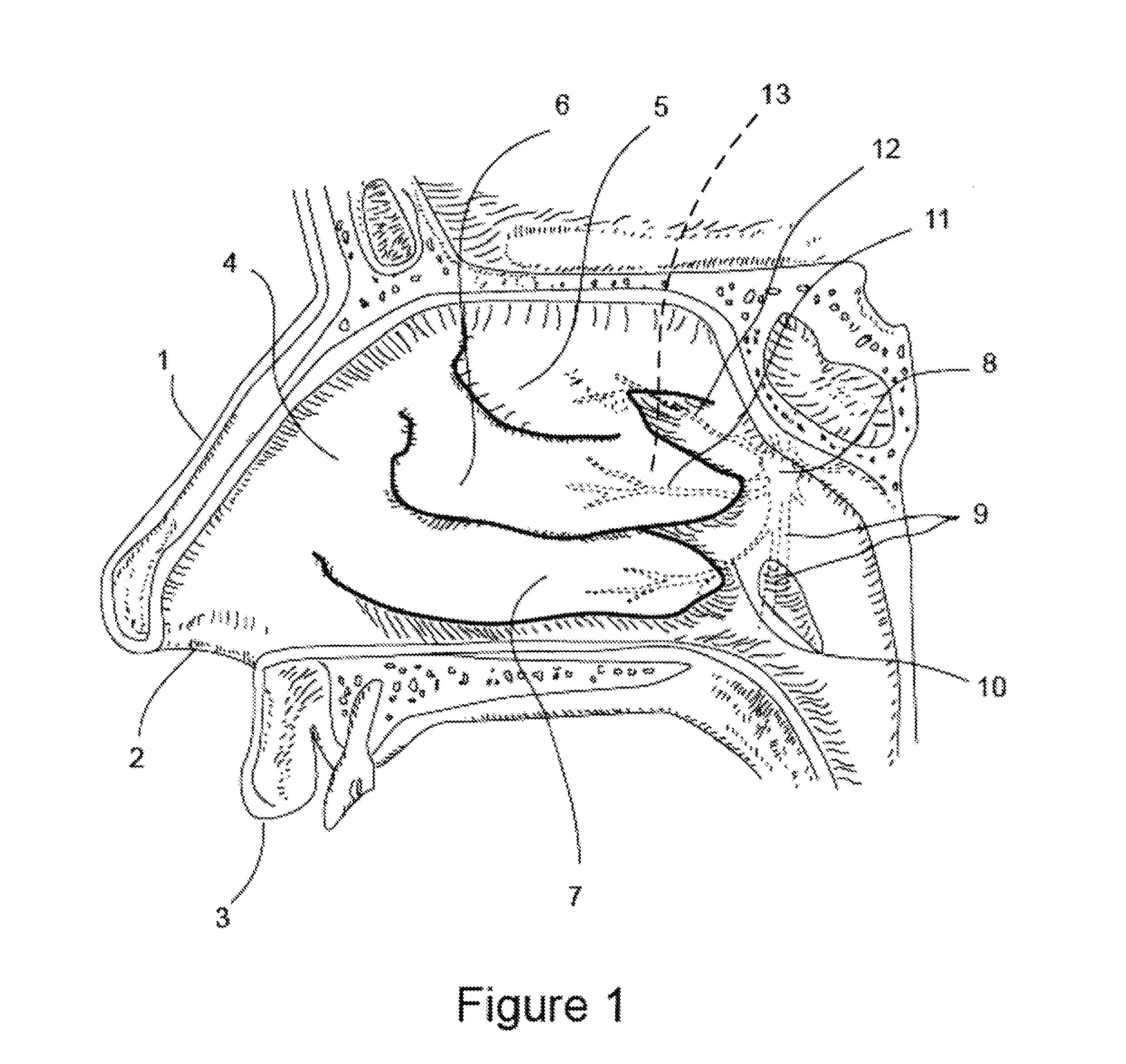
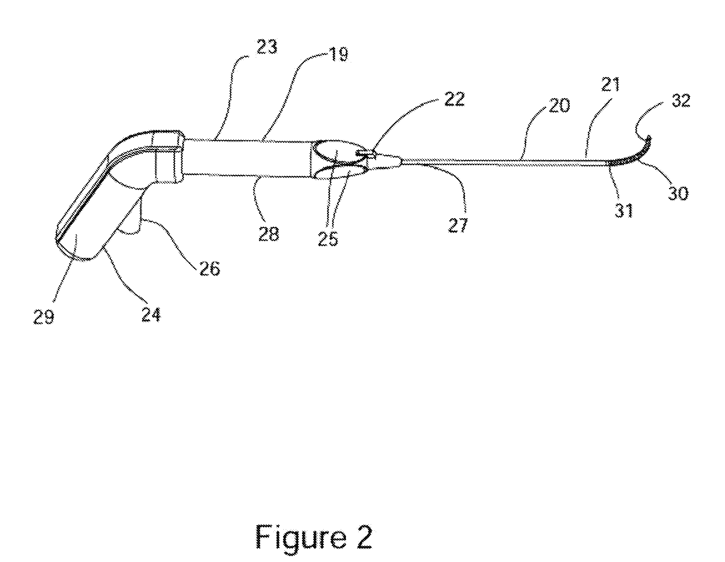
[0029]The evaporated cryogen may be exhausted into the room through the probe shaft to a vent port in the hand piece, or in the vicinity of the proximal end of the probe shaft. The surgical probe is configured so that the expandable membranous structure expands to a predetermined, shape in response to liquid cryogen evaporation. The pressure within the expandable membranous structure during cryogen evaporation may be regulated. The regulation means may comprise a pressure relief valve disposed in the gas exhaust path. The expandable membranous structure may be formed from an elastomeric material such as silicone rubber, or a urethane rubber. Alternatively, the expandable membranous structure may be formed from a substantially non-elastomeric material such as polyurethane or PET. The expandable membranous structure is configured so the shape and the size of the structure matches the shape and the size of the cul-de-sac of the lateral nasal wall defined by the tail of the middle turbinate, lateral nasal wall and the inferior turbinate, which is the target location for the ablation of the posterior nasal nerves for the treatment of rhinitis. Matching the size and shape of the expandable membranous structure to the size and shape of the target anatomy facilitates optimal tissue freezing and ablation of posterior nasal nerves. The expandable membranous structure may have an expanded diameter between approximately 3 mm and 12 mm in one radial axis, and may be configured such that the expanded diameter in one radial axis is different than another radial axis.

Problems solved by technology

Medical treatment has been shown to have limited effects for chronic rhinitis sufferers and requires daily medication use or onerous allergy treatments and up to 20% of patients may be refractory.
In addition to the medications turbinate reduction surgery (RF and micro-debridement) both have temporary duration of effect of 1-2 years and can result in complications including mucosal sloughing, acute pain and swelling, overtreatment and bone damage.
Additionally, turbinate reduction does not treat the symptom of rhinorrhea.
This pathophysiology has been confirmed as surgical treatment of the vidian nerve has been tried with great success; however, the procedure is invasive, time consuming and potentially can result in dry eyes due to autonomic fibers in the vidian nerve that supply the lacrimal glands.
However, the original technique was abandoned at the beginning of the 1980s because of its irreversible complications such as dry eyes.

Method used


Image

  • Apparatus and Methods for Treating Rhinitis
  • Apparatus and Methods for Treating Rhinitis
  • Apparatus and Methods for Treating Rhinitis

Examples


embodiment 270

[0181]The angle of deflection may be between approximately 60 to 120 degrees and may be configured for deflection in one direction, or in two directions as shown. The deflection means comprises at least one pull wire housed within probe shaft 267 and a deflection actuator disposed in the vicinity of the proximal end of probe 266. Those skilled in the art deflectable tipped surgical probes are familiar means for creating a deflectable tipped cryosurgical probe according to this invention. FIGS. 16C and 16D are schematic illustrations of the distal end of an alternative embodiment 270 of the cryosurgical probe where the cryo-ablation element 274 is configured for producing multiple discrete cryo-ablations simultaneously. Cryo ablation element 274 comprises an expansion chamber, not shown, discrete lateral cryo-ablation surfaces 272, surrounded by thermal insulation 273. Ablation element 274 comprises a hollow bullet shaped metallic structure with lateral protrusions in the surface for...

embodiment 287

[0182]FIG. 17A is a schematic illustration of the distal end of an alternative embodiment 280 of the cryosurgical probe comprising a semi-circular cryo-ablation element 282. Cryo-ablation element 282 comprises a continuation of probe shaft 281 formed in a semi-circle as shown. Within the semi-circular section cryogen delivery tube 283 comprises an array of lateral fenestration in the one axial direction relative to semi-circular form, making the corresponding surface of the ablation element 282 the cryo-ablation surface. FIG. 17B is a schematic illustration of the ablation 284 morphology in the nasal mucosa 288 resulting from use of the semi-circular ablation element 282. The gap 286 in the ablation provides blood perfusion to the mucosa encompassed by the ablation providing a reduction in tissue sloughing as the result of the ablation, as well as a reduction in the chance of infection, and a reduction of patient discomfort. FIG. 17C is a schematic illustration of the distal end of ...

embodiment 362

[0188]FIG. 22A is a schematic illustration of an alternative embodiment 377 of RF ablation probe 362 comprising a linear electrode array 378 disposed on a planar surface; a fluid irrigation ports 387 associated electrodes 379, and a deployable needle 380 configured for injecting a liquid into a sub-mucosal space. FIG. 22B is a schematic illustration of the distal end of the alternative embodiment 377 RF ablation probe showing the arrangement of the ablation electrodes 379 and the associated fluid irrigation ports 387. FIG. 22C is a schematic illustration of the distal end of the alternative embodiment377 RF ablation probe showing the arrangement of the ablation electrodes 379 and the associated fluid irrigation ports 387 with the needle 380 deployed. The function, of domed electrodes 379, fluid ports 387, electrical connector 343, fluid connector 344, RF activation switch 345, handle 382, and shaft 384 all function in essentially the same manner as described for prior embodiment 362...


PUM


Abstract

Apparatus and methods for treating conditions such as rhinitis are disclosed herein where a distal end of a probe shaft is introduced through the nasal cavity where the distal end has an end effector with a first configuration having a low-profile which is shaped to manipulate tissue within the nasal cavity. The distal end may be positioned into proximity of a tissue region having a post nasal nerve associated with a middle or inferior nasal turbinate. Once suitably positioned, the distal end may be reconfigured from the first configuration to a second configuration which is shaped to contact and follow the tissue region and the post nasal nerve may then be ablated via the distal end. Ablation may be performed using various mechanisms, such as cryotherapy, and optionally under direct visualization.

Description

CROSS-REFERENCES TO RELATED APPLICATIONS[0001]The present application is a Continuation of U.S. Ser. No. 14 / 503,060 filed Sep. 30, 2014; which claims priority to U.S. Provisional Patent Appln No. 61 / 884,547 filed Sep. 30, 2013; and 62 / 015,468 filed Jun. 22, 2014; the contents, each of which is incorporated herein by reference in its entirety for all purposes.FIELD OF THE INVENTION[0002]The present invention is related to devices and methods for ablating regions of tissue. More particularly, the present invention is related to devices and methods for ablating regions of tissue such as through cryogenic ablation of tissue regions within the nasal cavity for treating conditions such as rhinitis.BACKGROUND OF THE INVENTION[0003]The human nose is responsible for warming, humidifying and filtering inspired air. The nose is mainly formed of cartilage, bone, mucous membranes and skin. The right and left nasal cavities extend back to the soft palate, where they merge to form the posterior ch...

Claims


Application Information

Patent Timeline
Patent Type & Authority Applications(United States)
IPC IPC(8): A61B18/02A61B1/04A61N7/02A61B18/14
CPCA61B18/02A61B2218/002A61B1/04A61N7/022A61B2018/0022A61B2018/00327A61B2018/00434A61B2018/00577A61B2018/00714A61B2018/00791A61B2018/00982A61B2018/0212A61B2018/0268A61N2007/003A61B18/1485A61B17/24A61B2018/143A61B2018/1475A61B2090/378G01M3/24G01N29/265G01N29/07G01N2291/0258G01N29/0618G01N2291/0289G01N29/225G01N29/043G01N29/262A61N7/02
Inventor SAADAT, VAHID
Owner ARRINEX INC
Why Eureka
Try Eureka