Balloon catheter having a retractable sheath and locking mechanism with balloon recapture element

Active Publication Date: 2016-12-08
PIGOTT JOHN P
View PDF2 Cites 8 Cited by
  • Summary
  • Abstract
  • Description
  • Claims
  • Application Information

AI Technical Summary

Benefits of technology

[0007]Recently, medical practitioners have realized that drug coatings may be applied to the outer surface of the intravascular balloons to increase the effectiveness of medical treatment. These so called “drug coated balloons” are exposed to blood and other intravascular fluids upon being inserted into a person's vascular system. This may result in the premature activation, elution, dilution, and loss of the drug coating on the way to the treatment zone. Therefore, it would be desirable to provide a watertight seal between the balloon and the sheath such that the medicated balloon is not exposed to intravascular fluids until the balloon reaches the treatment zone.
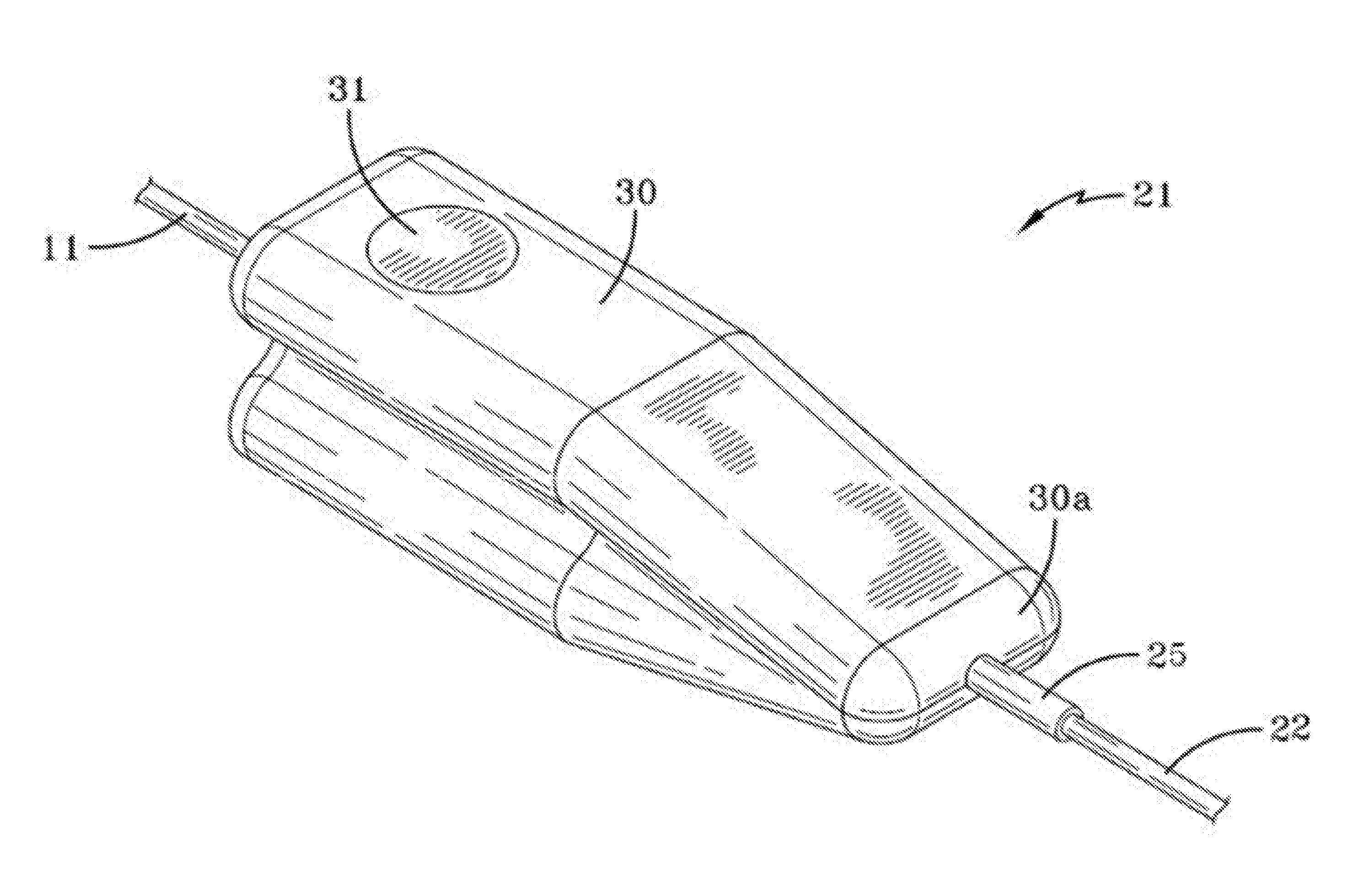
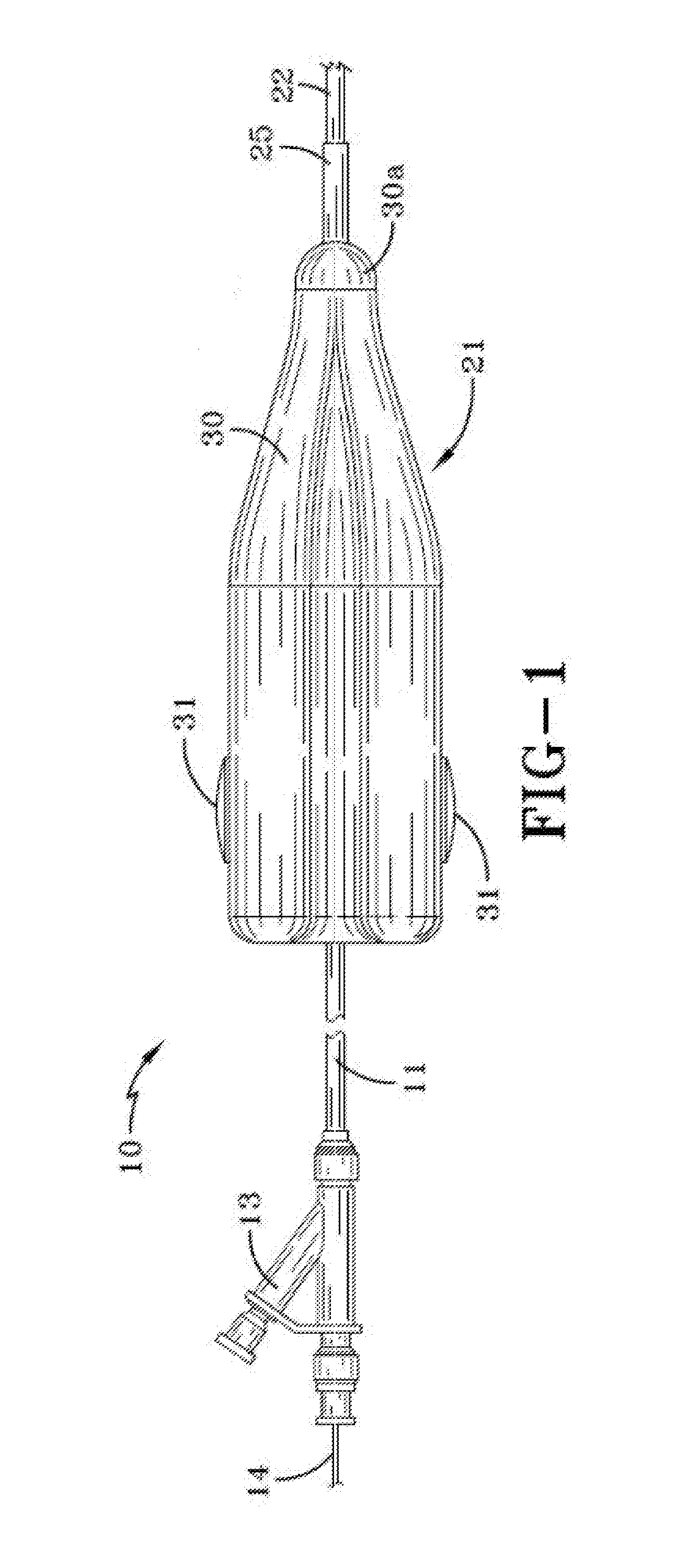
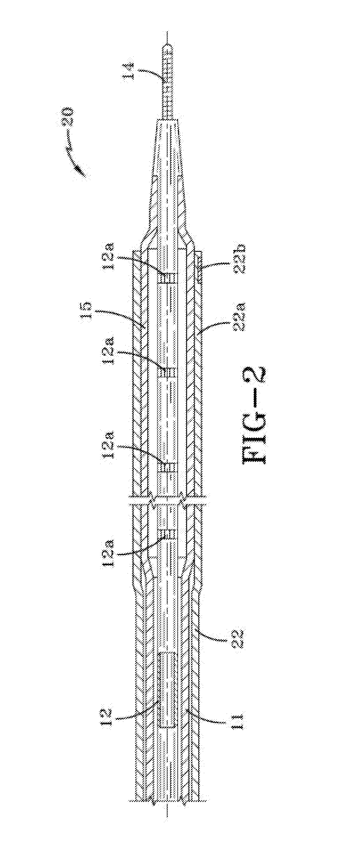
[0008]The present invention is directed to an improved structure for a balloon catheter having a retractable sheath that can quickly and easily adjust the length of the inflated portion of the balloon and a locking mechanism for selectively retaining the sheath in the desired position for use. The balloon catheter assembly includes an inner member and an outer member that is disposed about the inner member. The outer member includes an inflatable balloon. A sheath is disposed about the outer member for movement relative to the balloon so as to selectively expose some or all of the balloon for inflation. The balloon catheter assembly includes a clamp for selectively securing the sheath at a desired position relative to the balloon. The inner member may comprise a series of indentations or protrusion that engage the clamp such that the user may selectively control the location of the retractable sheath relative to the balloon.
[0009]The assembly may further include a mechanical stop that is configured to selectively secure the balloon and prevents it from entirely escaping the sheath when the balloon is inflated. The assembly may comprise a series of graduated markers, such as radiopaque markers, that indicate the position of the balloon relative to the retractable sheath. The balloon may further comprise a strength collar, such as an annulus, located on the distal end of the retractable sheath.
[0010]Additionally, the balloon and the sheath may form a substantially watertight engagement with one another. This seal may prevent the medicated coating from being prematurely r

Problems solved by technology

If a balloon catheter is too long, the balloon may damage the surrounding tissue.
If a balloon is too short, the treatment may be ineffective or require time-consuming repetition.
Here, the same phenomenon applies to a partially exposed balloon catheter from a sheath, though the situation is further complicated by the internal pressure of the balloo

Method used


Image

  • Balloon catheter having a retractable sheath and locking mechanism with balloon recapture element
  • Balloon catheter having a retractable sheath and locking mechanism with balloon recapture element
  • Balloon catheter having a retractable sheath and locking mechanism with balloon recapture element

Examples


Embodiment Construction

)

[0038]Various embodiments of the present invention will now be described in detail with reference to the accompanying drawings. In the following description, specific details such as detailed configuration and components are merely provided to assist the overall understanding of these embodiments of the present invention. Therefore, it should be apparent to those skilled in the art that various changes and modifications of the embodiments described herein can be made without departing from the scope and spirit of the present invention. In addition, descriptions of well-known functions and constructions are omitted for clarity and conciseness.

[0039]The invention is described more fully hereinafter with reference to the accompanying drawings, in which exemplary embodiments of the invention are shown. This invention may, however, be embodied in many different forms and should not be construed as limited to the exemplary embodiments set forth herein. Rather, these embodiments are provi...


PUM

PropertyMeasurementUnit
Lengthaaaaaaaaaa

Abstract

An intravascular balloon catheter device is disclosed having an inner member, an outer member disposed about the inner member and further comprising a balloon. A sheath is disposed about the outer member that moves relative to the balloon so as to selectively expose some or all of the balloon for inflation. A clamp may be used to selectively secure the sheath at a desired position relative to the balloon. A balloon recapture element may permit incremental adjustment to the balloon length and facilitate balloon recapture.

Description

CROSS-REFERENCE TO RELATED APPLICATION[0001]This application is a continuation-in-part of U.S. application Ser. No. 14 / 990,477 filed Jan. 7, 2016, which claims the benefit of U.S. Application No. 62 / 102,770, filed Jan. 13, 2015, and International Application No. PCT / US2014 / 046616, filed Jul. 15, 2014, which claims the benefit of U.S. Provisional Application No. 62 / 012,382, filed Jun. 15, 2014 and U.S. Provisional Application 61 / 846,095, filed Jul. 15, 2013. The disclosures of all of which are incorporated herein by reference as if restated in their entirety.TECHNICAL FIELD[0002]Exemplary embodiments of the present invention generally relate to balloon catheters used in surgical procedures.BACKGROUND AND SUMMARY OF THE INVENTION[0003]This invention relates in general to balloon catheters that are used in surgical procedures. In particular, this invention relates to an improved structure for such a balloon catheter having a retractable sheath that can quickly and easily adjust the len...

Claims


Application Information

Patent Timeline
IPC IPC(8): A61M25/10A61M25/00
CPCA61M25/1002A61M25/0045A61M2025/105A61M2025/1081A61M2025/1079A61M2025/1088A61M2025/0046A61M2025/1068A61M2025/1004A61M25/10
Inventor PIGOTT, JOHN P.
Owner PIGOTT JOHN P
Why Eureka
Try Eureka