Fused filament fabrication extruder

Inactive Publication Date: 2016-12-08
GORDON MARK CHRISTOPHER
View PDF4 Cites 14 Cited by
  • Summary
  • Abstract
  • Description
  • Claims
  • Application Information

AI Technical Summary

Problems solved by technology

This process results in high thermal capacitance, due to the heat conducting through the entire heater block and nozzle mass.
It also results in high thermal radiation waste heat, due to the relatively

Method used


Image

  • Fused filament fabrication extruder
  • Fused filament fabrication extruder
  • Fused filament fabrication extruder

Examples


Embodiment Construction

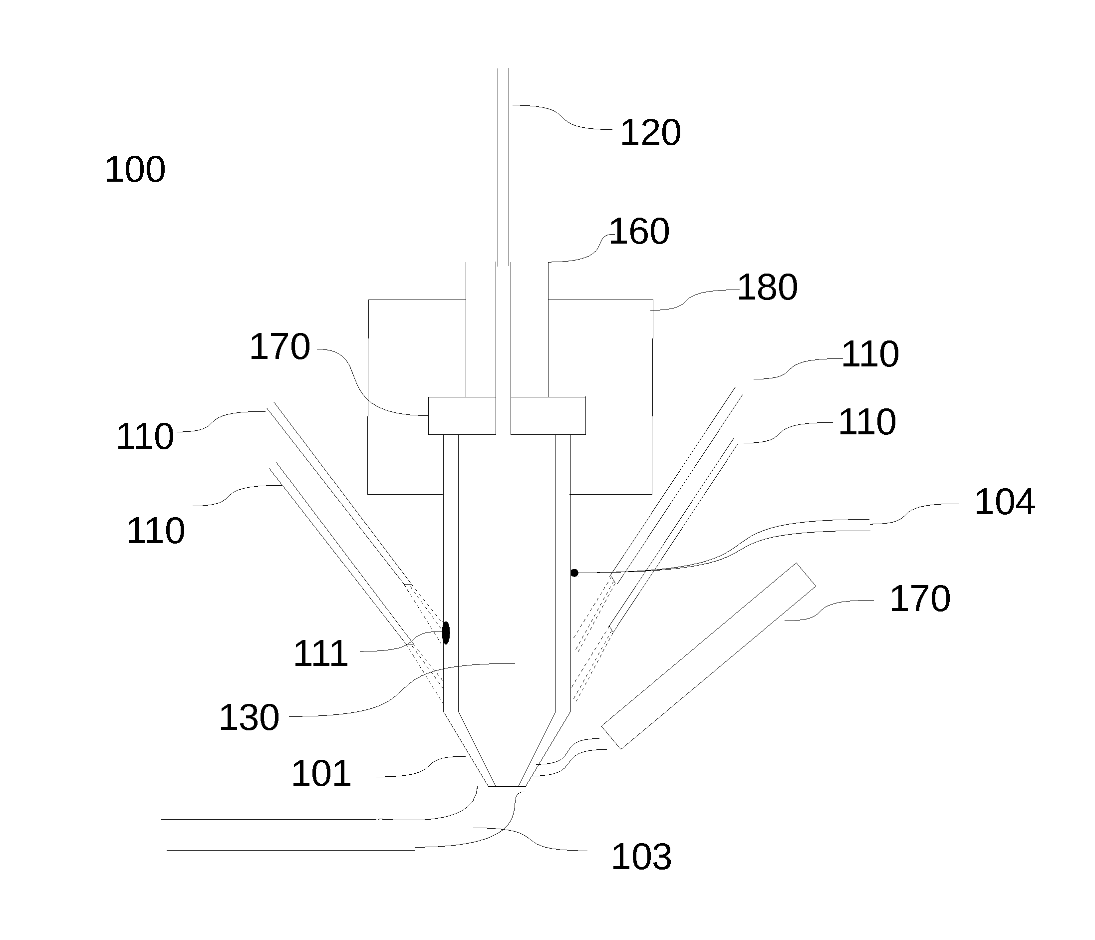
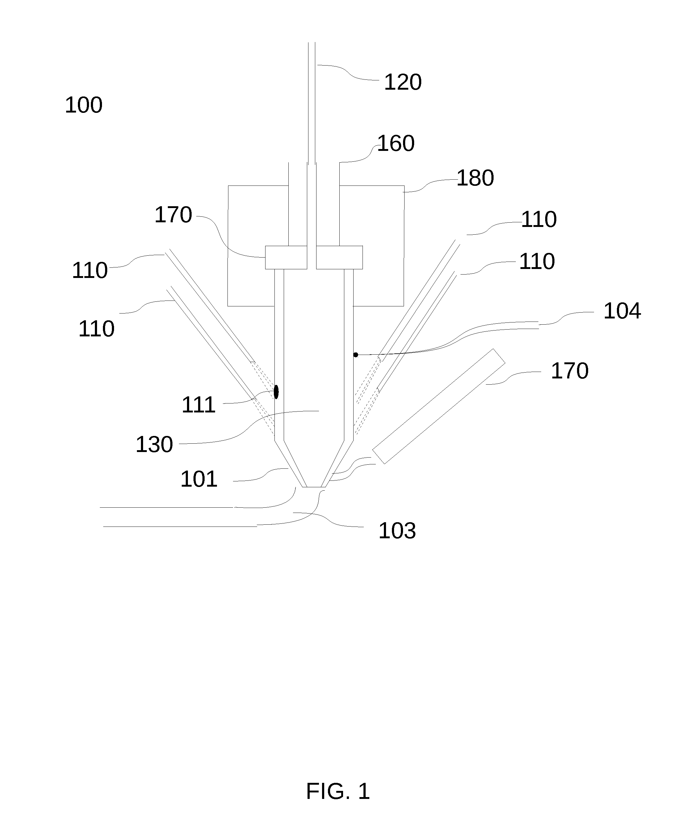
[0009]FIG. 1 illustrates a FFF hot end 100 of a FFF 3D printer according to embodiments of the present invention. In this embodiment, one or more non-contact heat sources 110 heat the FFF deposition nozzle 101. In an example embodiment non-contact heat sources 110 may be a laser. In this example embodiment, heat is generated directly by the laser excitation of the nozzle 101. The use of a laser heat source in this manner eliminates the need for heat transfer elements attached to the nozzle 101, such as a metal block or resistive heater.

[0010]The nozzle 101 extrudes a narrow strand of melted material 103. The material feedstock 120 is shown as a cylinder however it can be of any shape or size. In an embodiment the shape could be a ribbon or other thin profile to allow for faster heating of the material feedstock 120. Pressure is required to force the melted material through the nozzle 101.

[0011]Melt zone 130 is where the material feedstock 120 is liquefied by the heat of the nozzle 1...


PUM

PropertyMeasurementUnit
Temperatureaaaaaaaaaa
Fractionaaaaaaaaaa
Temperatureaaaaaaaaaa

Abstract

3D Fused Filament Fabrication (FFF) is improved by heating the deposition nozzle with one or more non-contact heat sources. 3D FFF is also improved by cooling the deposition nozzle with one or more active cooling elements. Temperature control of the deposition nozzle is improved due to the reduction in mass of the nozzle by eliminating conductive heat elements and their associated devices, such as thermal transfer blocks. Responsiveness of the nozzle is improved by using lasers as non-contact heating sources, allow for rapid changes in temperature when necessary.

Description

BACKGROUND[0001]1. Field[0002]The present invention relates to additive 3D fabrication, and, more particularly, to a fused filament fabrication extruder.[0003]2. Description of the Related Art[0004]The extrusion point of a Fused Filament Fabrication (FFF) 3D printer is commonly referred to as a hot end. In these printers, the hot end heats the material being extruded to create a 3D object. The hot end is typically connected to a 3 axis carriage which is typically a Cartesian or polar coordinate arrangement, and allow movement of a FFF deposition head freely in 3D space. Typically, the source of heat used to melt the extruded material is a conductive heater in contact with a heater block connected with the nozzle or liquefier tube feeding the nozzle. Heat is then spread primarily via conduction from the heat source to the nozzle. This process results in high thermal capacitance, due to the heat conducting through the entire heater block and nozzle mass. It also results in high therma...

Claims


Application Information

Patent Timeline
IPC IPC(8): B29C67/00
CPCB29C67/0055B33Y10/00B33Y30/00B29C67/0085B29C35/0805B29C2035/0838B29C64/209B29C64/118B29C64/106
Inventor GORDON, MARK CHRISTOPHER
Owner GORDON MARK CHRISTOPHER
Why Eureka
Try Eureka