Abutment Plate for Water Control Gate

Inactive Publication Date: 2016-12-08
OBERMEYER HENRY
View PDF6 Cites 0 Cited by
  • Summary
  • Abstract
  • Description
  • Claims
  • Application Information

AI Technical Summary

Benefits of technology

[0027]In accordance with a further aspect of the invention, the lateral clearances provided between guide rails and abutment plate strips may be filled prior to concrete placement, preferably at the factory, with a low

Problems solved by technology

The principal challenge to using it as an abutment plate is that it has a much higher coefficient of thermal expansion than concrete and also has a relatively high Young's modulus.
If rigidly fixed to a concrete structure the differential expansion of UHMW polyethylene and concrete may cause the concrete to br

Method used


Image

  • Abutment Plate for Water Control Gate
  • Abutment Plate for Water Control Gate
  • Abutment Plate for Water Control Gate

Examples


Embodiment Construction

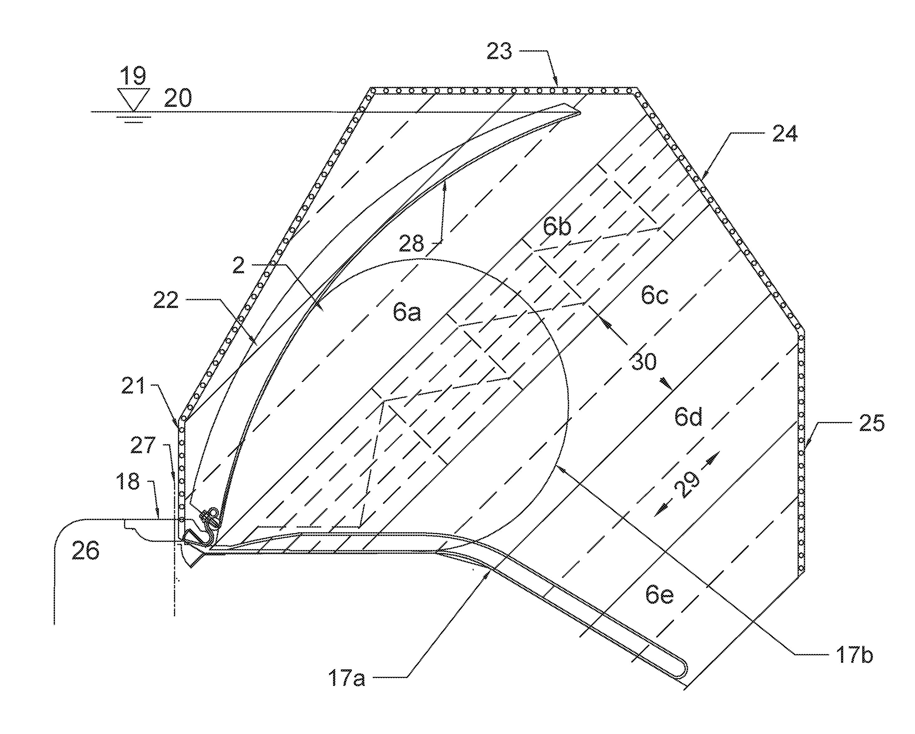
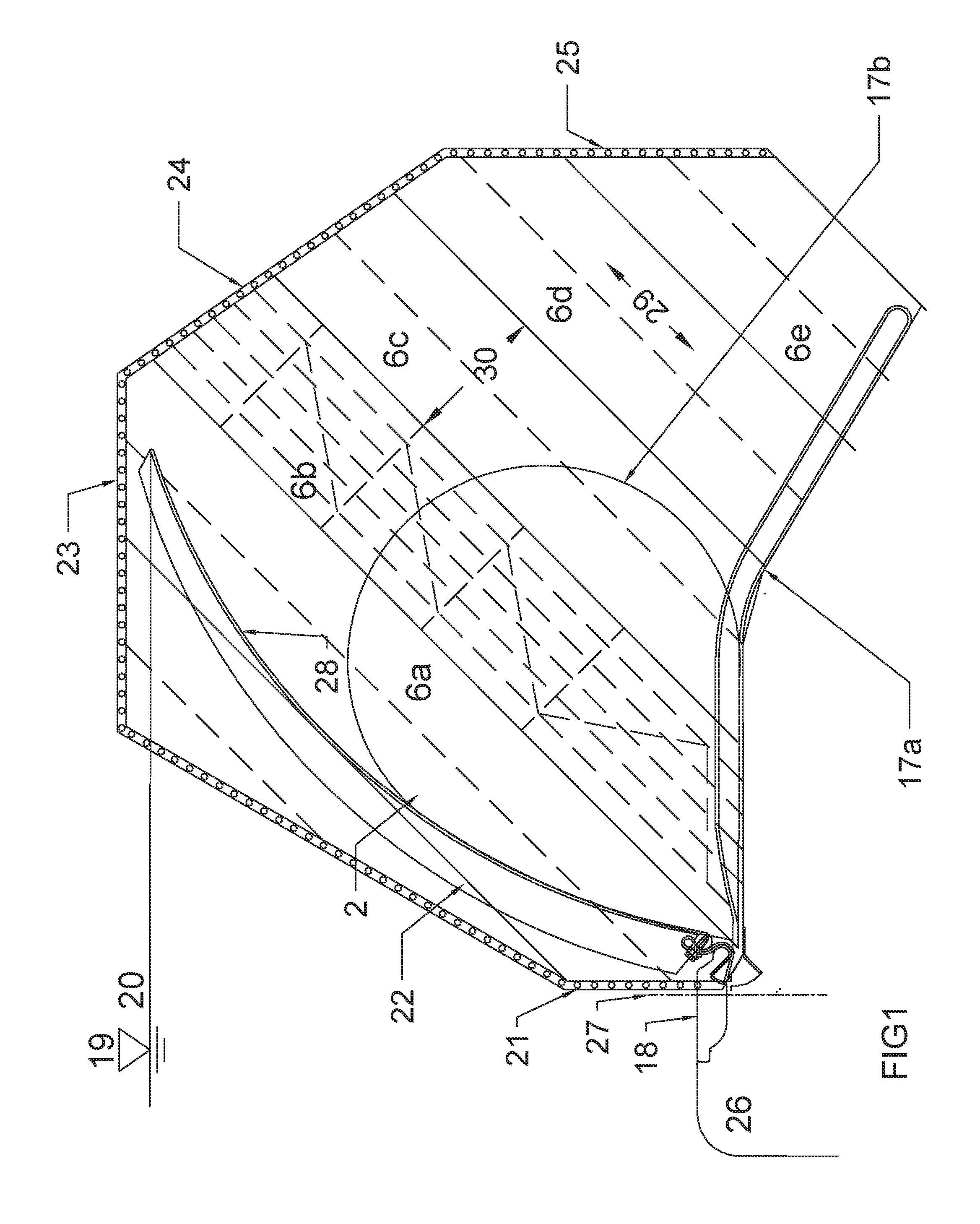
[0035]Referring to FIG. 1, Abutment plate 6a, 6b, 6c, 6d, and 6e are attached to concrete abutment 19. Inflated air bladder 17b actuates gate panel 28 to which is affixed abutment seal 2. The upstream edges of abutment plate strip 6a are clamped to concrete abutment 19 by clamps 21 and 22. The remaining edges of the abutment plate strips 6a, 6b, 6c, 6d and 6e are secured by clamps 23, 25, and 25. The abutment plate of this invention is applicable to a wide variety of water control gates in addition to the one illustrated.

[0036]Referring now to FIG. 2, a cross section of an abutment plate assembly is shown. Guide rails 12a, 12b, 12c, 12d and 12e secure abutment plate 6b to concrete pier 19. Clearances 7, 8, 9, and 10 vary in proportion to distance from the center rail 12c where only minimal clearance need be provided. The rails are connected, by welding for example, to spacer member 13 which may in turn be connected to diagonal brace 14.

[0037]Referring now to FIG. 3, clamp 22 secures...


PUM


Abstract

The invention relates to a friction reduced and ice resistant water control gate abutment plates that permit, without damage to the concrete, large relative thermal movement between the abutment plate assembly and the concrete abutment or pier to which the assembly is attached. Features that provide ease of maintenance, tight sealing and debris damage resistance are also disclosed.

Description

BACKGROUND OF THE INVENTION1. Field of Invention[0001]The present invention relates to abutment plates for water control gates specially adapted to controlling rivers and canals and especially wherein such gates are subject to freezing conditions.2. Description of Related Art[0002]UHMW polyethylene may be used as an abutment plate for bottom hinged water control gates. In small sizes, for example 1 to 2 meters across, closely spaced bolts may be used to secure such (one piece) abutment plates with loosely fitting bolts. The close spacing of the bolts prevents thermal buckling of the abutment plates, while clearance between the bolts and the clearance holes in the UHMW abutment plates allows for limited thermal movement of the abutment plate relative to the underlying structure. Clearance at the bolts prevents undue stresses from being generated as a result of thermal size changes of the abutment plate. Alternatively, springs may be used to secure a UHMW abutment plate to a concrete ...

Claims


Application Information

Patent Timeline
IPC IPC(8): E02B5/08E02B7/28E02B7/54E02B7/50
CPCE02B5/082E02B7/54E02B7/28E02B7/50E02C1/08E02B3/16E02B17/0021
Inventor OBERMEYER, HENRYECKMAN, ROBERT
Owner OBERMEYER HENRY
Why Eureka
Try Eureka