Cell for storing power, comprising at least one male element and one female element equipped with electrical connection interfaces

a cell and power technology, applied in the field of cell storage power, can solve the problems of increasing the risk of short circuit, and high risk to the health of the operator and the proper operation of the cell,

Active Publication Date: 2016-12-08
COMMISSARIAT A LENERGIE ATOMIQUE ET AUX ENERGIES ALTERNATIVES
View PDF3 Cites 6 Cited by
  • Summary
  • Abstract
  • Description
  • Claims
  • Application Information

AI Technical Summary

Benefits of technology

[0019]Thanks to the invention, it is possible to carry out a simple and safe assembly of several cells for storing power in accordance with the invention in an electrical module for assembling a power storage system, by the intermediary of the male and female elements that nest into one another. The connection interfaces being located on the male and female elements, they can be difficult to access, even inaccessible, by the outside environment, and in particular by an operator, which can advantageously make it possible to suppress the risks, in particular of a court-circuit.
[0064]The method of manufacturing according to the invention can advantageously make it possible to carry out the cell with the least amount of elements and the least amount of operations possible. To do this, the method uses preferentially steps of injecting, overmoulding and / or of powder metallurgy, using an electrical core, in particular electrochemical, for example a stack or a spool carried out beforehand.

Problems solved by technology

These types of electrical connection systems are however not very satisfactory due to their dangerousness, in particular in the field of power elements, both for the operators and for the storage cell itself.
Indeed, the external conductive part and the apparent terminals increase the risks of a short circuit.
However, as indicated hereinabove, this type of cell causes high risks for the health of the operator and the proper operation of the cell, in particular in the case of a high-energy cell.
The risks for the operator are of an electrical nature and caused by the possibility of being able to touch the two terminals or conductive parts in contact with the terminals.
In addition, the risks for the cell are to obtain a short-circuiting of the two terminals which can result in the degradation or a substantial heating of the cell.

Method used


Image

  • Cell for storing power, comprising at least one male element and one female element equipped with electrical connection interfaces
  • Cell for storing power, comprising at least one male element and one female element equipped with electrical connection interfaces
  • Cell for storing power, comprising at least one male element and one female element equipped with electrical connection interfaces

Examples


fourth embodiment

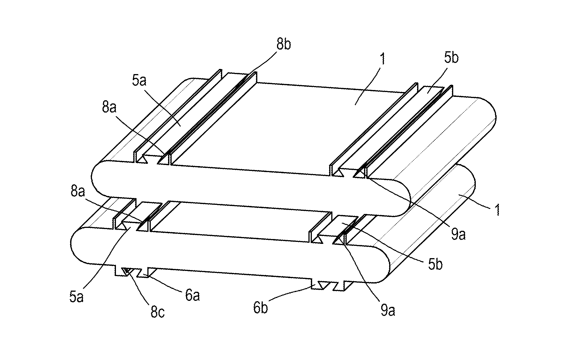
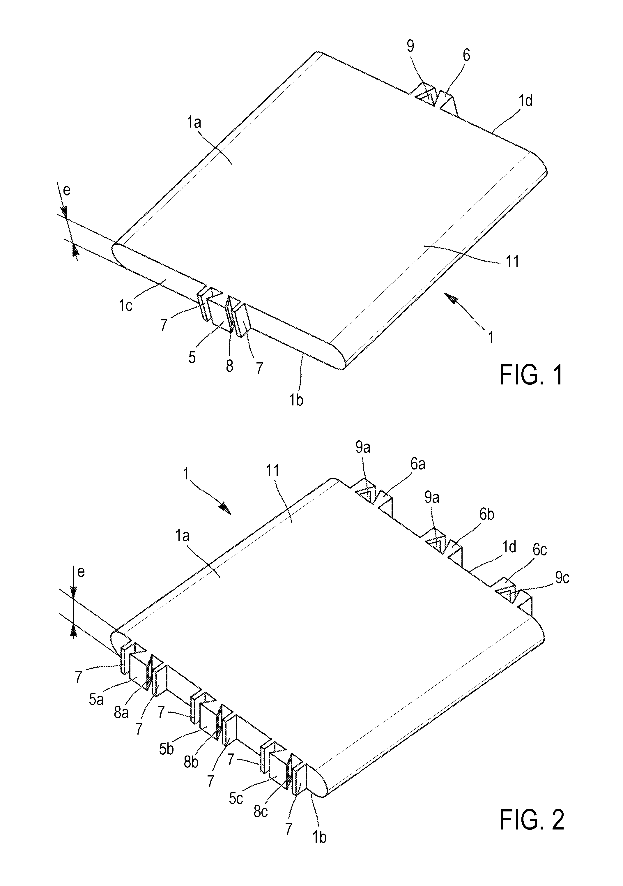
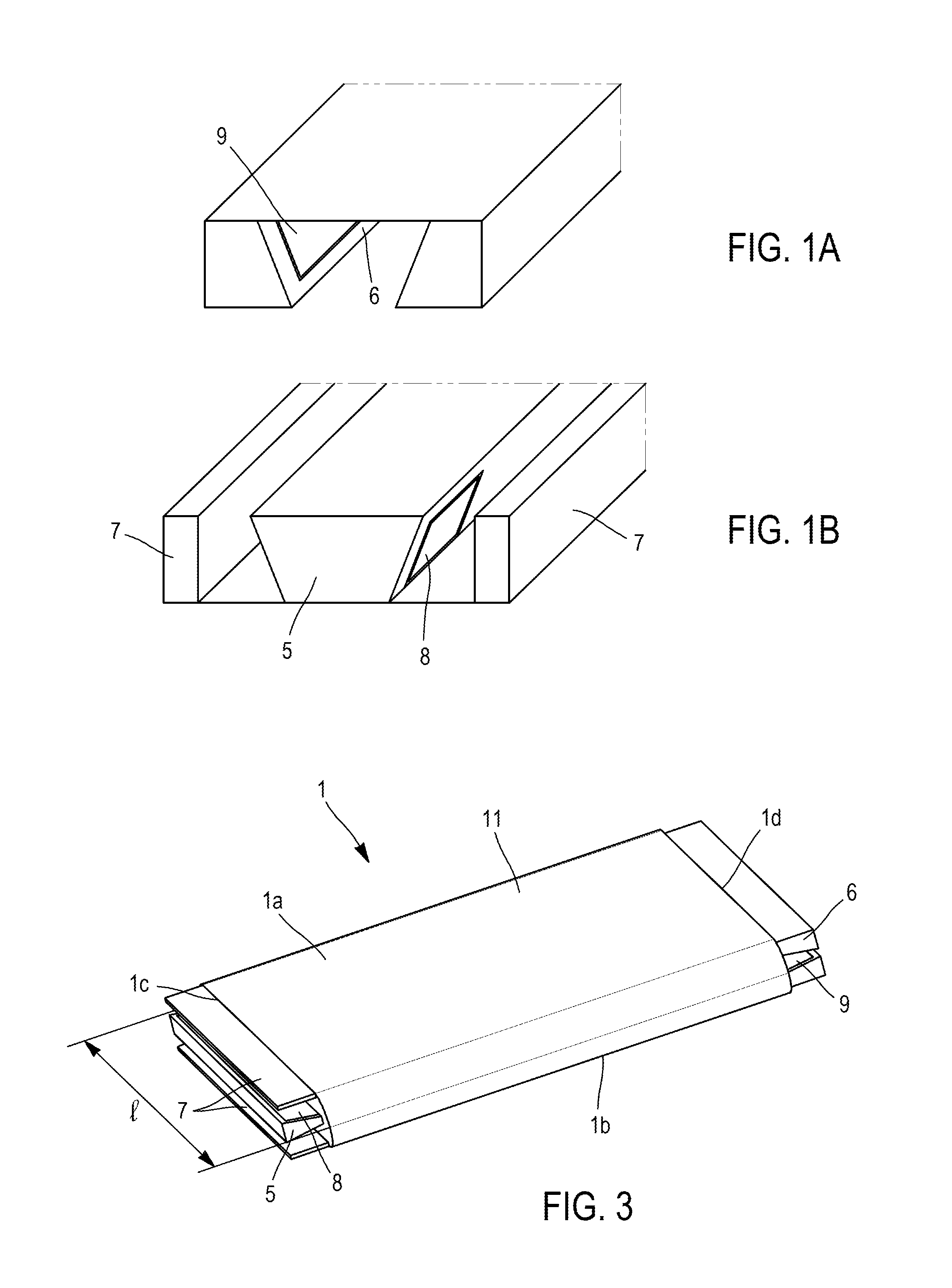
[0084]FIG. 10 shows, in perspective, a cell for storing power in accordance with the invention,

[0085]FIG. 11 shows, in perspective and diagrammatically, the composition of a cell of the type of that of FIG. 10,

fifth embodiment

[0086]FIG. 12 shows, in perspective, a cell for storing power in accordance with the invention,

[0087]FIG. 13 shows, in perspective, a first principle of maintaining in position of cells for storing power in accordance with the invention,

[0088]FIGS. 14A and 14B show, in perspective, a second principle for maintaining in position of cells for storing power in accordance with the invention,

[0089]FIGS. 15A and 15B show, respectively with non-visibility and visibility in transparency of the electrochemical cores of the cells, a bottom view of an assembly in parallel of two cells for storing power in accordance with the invention,

[0090]FIGS. 16A and 16B show, respectively with non-visibility and visibility in transparency of the electrochemical cores of the cells, a top view of the assemblage in parallel of the two cells of FIGS. 15A and 15B,

[0091]FIGS. 17A and 17B show, respectively with non-visibility and visibility in transparency of the electrochemical cores of the cells, a top view o...

sixth embodiment

[0093]FIG. 19 shows, in perspective and with visibility of the electrochemical core, a cell for storing power in accordance with the invention,

[0094]FIGS. 20A to 20G show, in perspective, different successive steps of implementing a first alternative to the method of manufacture in accordance with the invention,

[0095]FIGS. 21A to 21H show, in perspective, different successive steps of implementing a second alternative to the method of manufacture in accordance with the invention, and

[0096]FIGS. 22A to 22F show, in perspective, different successive steps of implementing a third alternative to the method of manufacture in accordance with the invention.

[0097]In all of these figures, identical references can designate identical or similar elements.

[0098]In addition, the various portions shown in the figures are not necessarily shown to a uniform scale, in order to make the figures more legible.

DETAILED DESCRIPTION OF PARTICULAR EMBODIMENTS

[0099]In all of the examples described hereinaft...


PUM

PropertyMeasurementUnit
number of degrees of freedomaaaaaaaaaa
temperatureaaaaaaaaaa
polarityaaaaaaaaaa

Abstract

The invention primarily relates to a cell (1) for storing power, which is to be integrated in an electrical module for assembling a power storage system, having a first surface (1a; 1c) and a second surface (1b; 1d), characterised in that the cell (1) comprises at least one male element (5; 5a, 5b, 5c) on one of the first (1a; 1c) and second (1b; 1d) surfaces thereof, and at least one female element (6; 6a, 6b, 6c) on the other of the first (1a; 1c) and second (1b; 1d) surfaces thereof, which elements are shaped such as to be fitted into one another such that the cell (1) is configured such as to be assembled to another cell (1) of the same type, in that at least one male element (5; 5a, 5b, 5c) comprises at least one electrical connection interface having positive polarity (8; 8a, 8b, 8c) and in that at least one female element (6; 6a, 6b, 6c) comprises at least one electrical connection interface having negative polarity (9; 9a, 9b), or conversely such that the cell (1) is configured such as to be electrically connected to another cell (1) of the same type.

Description

TECHNICAL FIELD[0001]This invention relates to the field of cells for storing power, and in particular to the field of elementary electrochemical cells. Such cells are intended to be assembled in modules which are themselves assembled together to form a power storage system, for example a battery pack. More particularly, the invention relates to the field of assembly and electrical connection systems integrated into such cells for storing power.[0002]The invention applies preferentially to elementary electrochemical cells that form electrochemical generators. However, it can also relate to capacitors and electrochemical or dielectric supercapacitors, for example.[0003]It has applications in many fields of industry, in particular for stationary or on-board applications, in particular for the field of electrical power of transport, land, air and / or sea vehicles, for example for the electrical power of hybrid and / or electrical vehicles for which an arrangement of a large number of cell...

Claims


Application Information

Patent Timeline
Patent Type & Authority Applications(United States)
IPC IPC(8): H01M6/42H01M2/20H01M2/26H01M2/30H01M2/02H01M2/10H01M50/121H01M50/202H01M50/209H01M50/262H01M50/517H01M50/538H01M50/553
CPCH01M6/42H01M2/0245H01M2/1077H01M2220/20H01M2/30H01M2/202H01M2/263H01M10/0431Y02E60/10H01M50/258H01M50/538Y02P70/50H01M50/209H01M50/121H01M50/517H01M50/202H01M50/553H01M50/262
Inventor BERTHE DE POMMERY, YVESAZAIS, PHILIPPEPICARD, LIONELTURIN, GUILLAUME
Owner COMMISSARIAT A LENERGIE ATOMIQUE ET AUX ENERGIES ALTERNATIVES
Why Eureka
Try Eureka