Systems and methods for transmission and reception of radio waves in a focal plane antenna array

a technology of focal plane antenna array and transmission and reception, applied in the field of communication systems, can solve the problems of heavy congestion across the allocated spread spectrum, and achieve the effect of maximizing the received signal and enhancing the received helical wave fron

Active Publication Date: 2016-12-08
AMRITA VISHWA VIDYAPEETHAM
View PDF3 Cites 21 Cited by
  • Summary
  • Abstract
  • Description
  • Claims
  • Application Information

AI Technical Summary

Benefits of technology

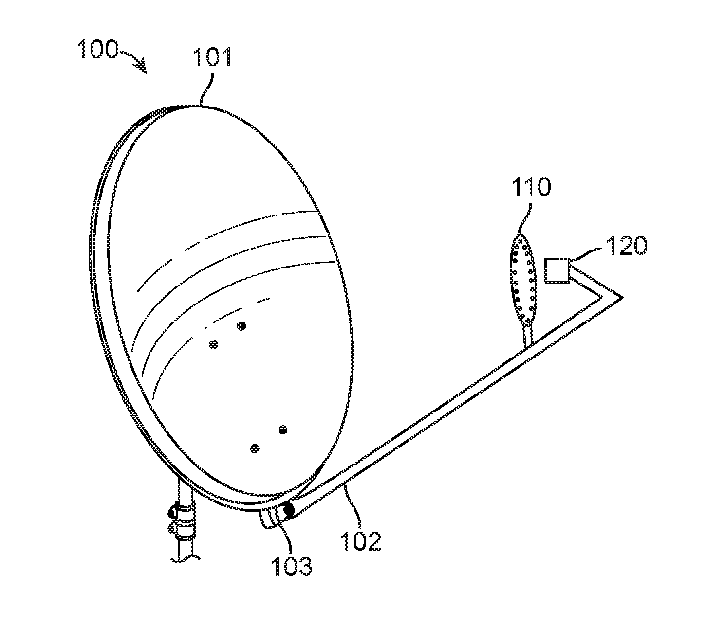
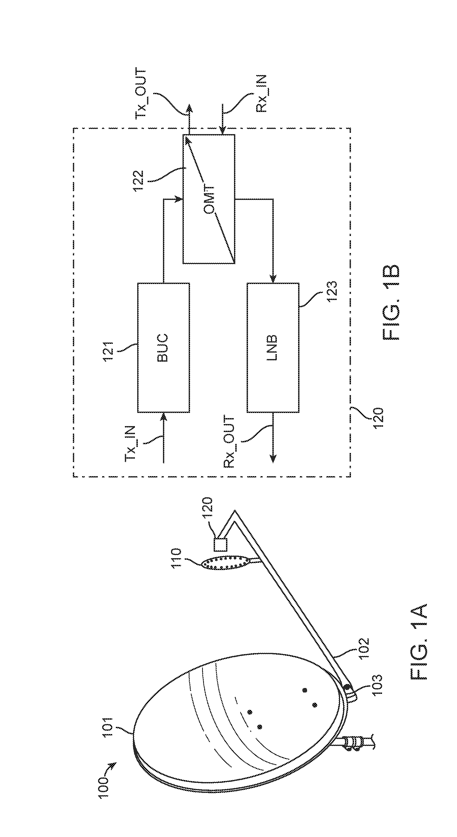
[0010]In one aspect, a focal plane antenna array system for transmitting and receiving radio waves comprises a parabolic dish and a focal plane antenna array. Further, the focal plane antenna array configuration comprises one or more antenna elements arranged in a circular array configuration with N array elements positioned along a circumference of M rings with a distance between each element. The array elements are coupled to a focal disc positioned along a focal plane of the parabolic dish such that the array is configured to, transmit radio beam patterns with one or more orbital angular momentum (OAM) states ‘l’ via a transceiver feed assembly coupled to the parabolic dish. The transceiver comprises a transmitter adapted to alter excitation phase of the radio beams of successive elements to generate helical wave fronts in the far-field. Further, the system is configured to receive radio beam patterns with one or more orbital angular momentum (OAM) states via a transceiver feed assembly coupled to the parabolic dish. The transceiver comprises a receiver adapted to enhance the received helical wave fronts optimally to maximize the received signal and calculate a total field received by the array configuration through superposition of the fields received by each of the elements.
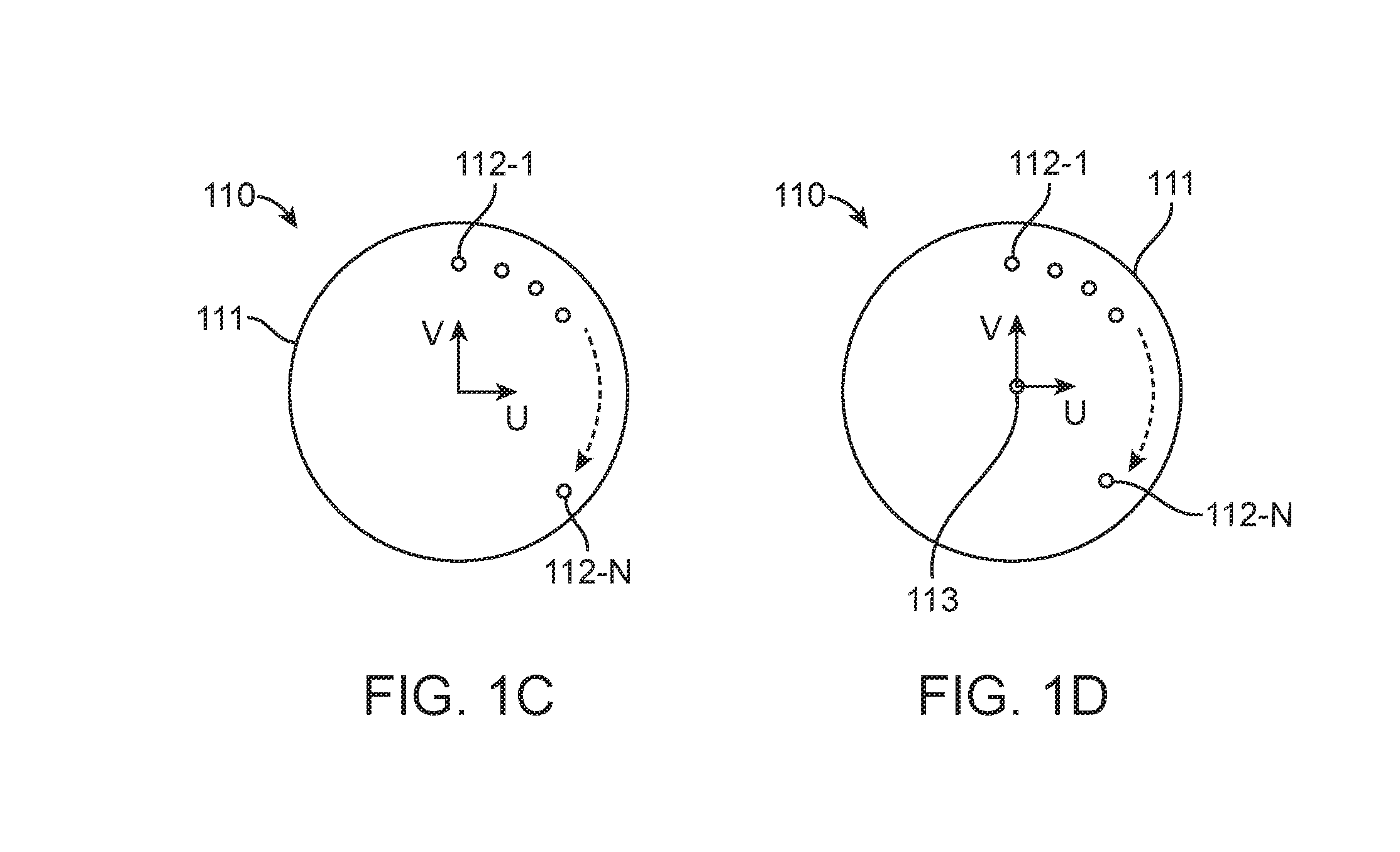
[0011]In another aspect, the circular array configuration is one of a uniform circular array-Type I with N equidistantly placed array elements, where M is 1; a uniform circular centred array-Type II with N equidistantly place array elements, where M is 1 and further including a centrally place element; a planar uniform circular array-Type II, with N array elements arranged equidistantly in M rings where M>1, or planar uniform circular centred array-Type IV with N array elements arranged equidistantly in M rings where M>1 and further including a centrally placed element. The one or more OAM states are in a range: −N / 2<l<N / 2. 4, further the OAM states bound transmission of the generated helical wave fronts corresponding to a value ‘l’ selected from 0, 2, or 4. The antenna array elements are configured to control the current and phase for each element to increase the total field, where the total field Etotal is obtained by Etotal=Esingleelement×AF wherein, AF is array factor and Esingleelement the field from one single element.

Problems solved by technology

As the number of remote terminals increases there may be heavy congestion across the allocated spread spectrum.

Method used


Image

  • Systems and methods for transmission and reception of radio waves in a focal plane antenna array
  • Systems and methods for transmission and reception of radio waves in a focal plane antenna array
  • Systems and methods for transmission and reception of radio waves in a focal plane antenna array

Examples


example 1

[0054]The geometry of various circular array configurations is described herein with examples. In an example of a uniform circular array-Type I configuration is shown in FIG. 3A, including nineteen elements along the circumference arranged on a focal disc along a focal plane. The uniform circular array-Type I configuration includes nineteen elements N=1 to 19 that are positioned along the circumference of the focal disc, spaced equidistant along the circumference of a circle with radius equal to 1.98 times of the wavelength and the distance between the elements is 0.65 times the wavelength.

[0055]FIG. 3B illustrates an example of a planar uniform circular array-Type III with 10 antenna elements in ring 1 and 9 antenna element in ring 2, and the ring 1 and the ring 2 are arranged on a focal disc along a focal plane. The planar uniform circular array-Type III configuration includes one or more antenna elements arranged in concentric circle such that the antenna elements N=10 to 18 are ...


PUM


Abstract

Systems and methods for transmitting and receiving radio waves includes a parabolic dish, a focal plane antenna array configuration antenna elements arranged in a circular array configuration with array elements positioned along circumference of rings with a distance between each element and coupled a focal disc positioned along a focal plane of the parabolic dish. The array is configured to transmit and receive radio beam patterns with one or more Orbital Angular Momentum states ‘l’ via a transceiver feed assembly. The transceiver includes a transmitter adapted to alter excitation phase of the radio beams of successive elements and generate helical wave fronts in the far-field, and a receiver to enhance the received wave fronts. A total field received by the array configuration is then calculated by a superposition of the fields received by each of the elements.

Description

CROSS-REFERENCE TO RELATED APPLICATIONS[0001]This application claims priority to Indian provisional patent application No. 1790 / CHE / 2015 filed on Apr. 3, 2015, the full disclosure of which is incorporated herein by reference.FIELD OF THE INVENTION[0002]The present disclosure relates generally to communication systems in particular to focal plane antenna array configurations for transmission and reception of radio waves using orbital angular momentum (OAM).DESCRIPTION OF THE RELATED ART[0003]Communication systems include various subsystems such as transmitter, receiver, channel encoder and decoder, and an antenna, to communicate with other remote terminals via wired or wireless mode of operation with the available spread spectrum. As the number of remote terminals increases there may be heavy congestion across the allocated spread spectrum. Such heavy congestion has led toward research into better ways of utilizing given spectrum. Since wireless communication has become ubiquitous, t...

Claims


Application Information

Patent Timeline
Patent Type & Authority Applications(United States)
IPC IPC(8): H01Q15/16H01Q1/24H01Q1/36
CPCH01Q15/16H01Q1/24H01Q1/36H01Q19/13H01Q15/244H04L5/04
Inventor SUNDARAM, G A SHANMUGHA
Owner AMRITA VISHWA VIDYAPEETHAM
Why Eureka
Try Eureka