
Actuated pin antenna reflector

a technology of antenna reflector and actuator, which is applied in the direction of antennas, antenna details, electrical equipment, etc., can solve the problems of not being able to gain full use from these novel software defined radio systems, and failing to generate an antenna system which would allow it to function to its full potential, so as to increase the signal to noise ratio of received signals, improve performance, and maximize the amplitude of received signals

Inactive Publication Date: 2017-02-21
THE UNITED STATES OF AMERICA AS REPRESETNED BY THE SEC OF THE AIR FORCE
View PDF10 Cites 0 Cited by
  • Summary
  • Abstract
  • Description
  • Claims
  • Application Information

AI Technical Summary

Benefits of technology

The system enhances signal reception and directionality by dynamically adjusting the antenna geometry, effectively mitigating interference and atmospheric distortions, and can be used in applications like satellite communications and radio astronomy, while also enabling precise prototyping and fabrication of reflector shapes.

Problems solved by technology

The prior art has embarked upon a quest to engineer this very approach but while it has succeeded in building software defined (thus highly adaptive) radios, it has failed to generate an antenna system which would allow it to function to its full potential.
Specifically, the prior art still utilizes standard hardware such as patch antennas, and therefore still unable to gain full usage from these novel software defined radio systems.

Method used


Image

  • Actuated pin antenna reflector
  • Actuated pin antenna reflector
  • Actuated pin antenna reflector

Examples


Embodiment Construction

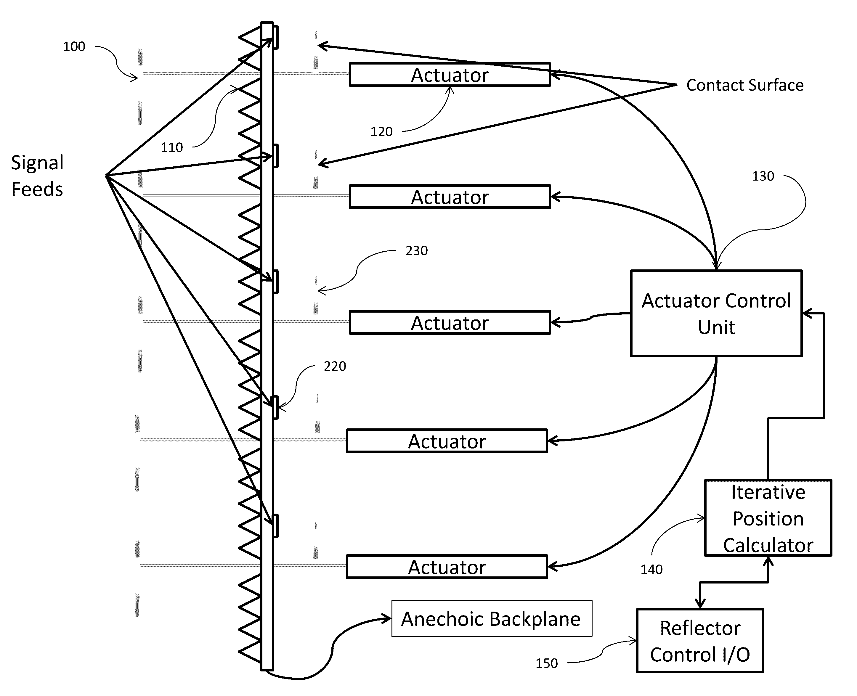
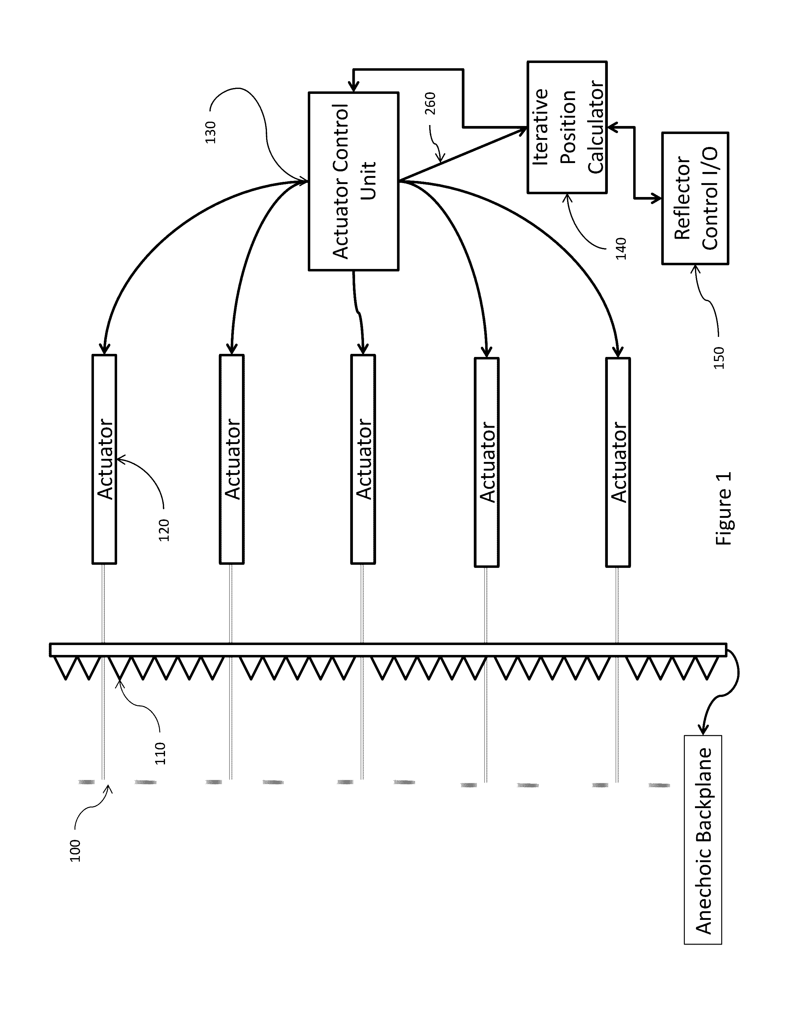
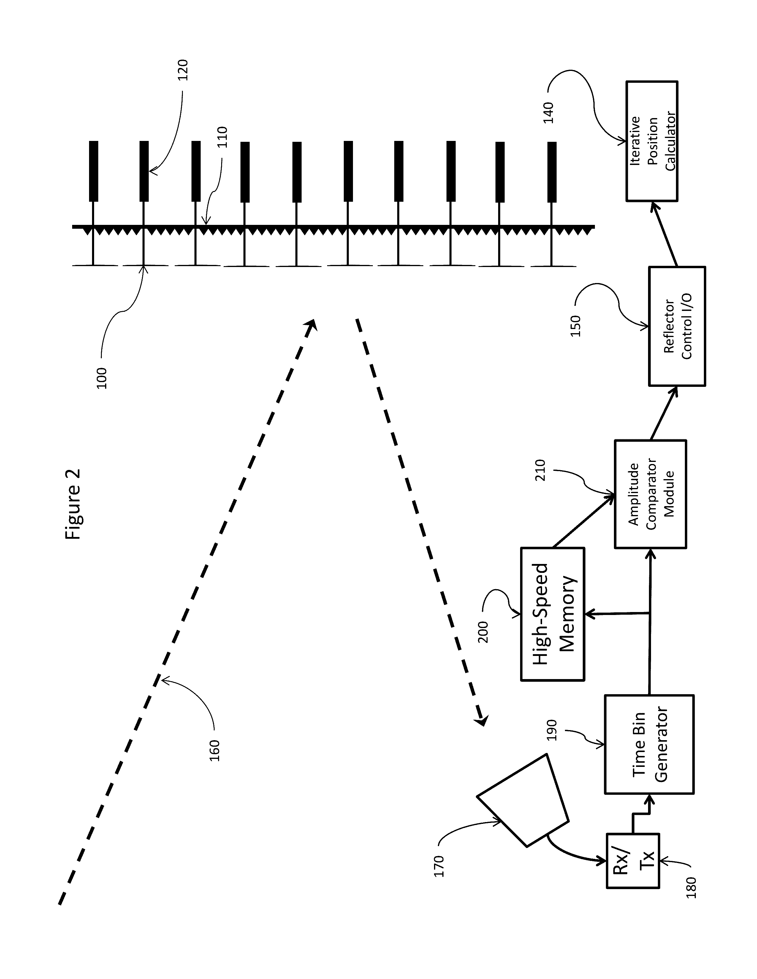
[0025]Referring now to FIG. 1, FIG. 2, and FIG. 3 describes the preferred embodiment of the present invention.

[0026]FIG. 1 shows a detail of the overall system illustrating the main novel points of the present invention. The broad head pins 100 make up the reflecting surface and it is the adjustment of the position of these pins which yields alterable overall geometry of the reflector. Behind the array of pins is an anechoic backplane 110 which helps isolate the reflecting surface and reduce any unwanted secondary reflections. Behind the backplane the pins are each attached to a precise, electrically controlled linear actuator 120 which serves as the motivator for the individual pins. In order to control the whole array of actuators the Actuator Control Unit (ACU) 130 contains the addressing and interface for each actuator, and is able to send the correct control signal to the correct actuator for any given position set. It also time-stamps the start and stop for pin movement time, ...


PUM


Abstract

Apparatus for improving the performance and allowing increased directionality of reflecting-type antenna systems by varying the geometry of the reflecting surface. A reflecting surface is composed of an array of actuated pins which are capable of extending or retracting to alter the overall pattern. An actuator controlling unit has the address of each actuator and is able to extend or retract the pins to the desired degree. The specific pattern which the actuator control unit realizes is determined by the iterative position calculator which utilizes directional inputs from the user and / or inputs from a system which determines the effectiveness of previous pin movements. The apparatus attempts to maximize the received signal by assessing amplitude changes over time and utilizing that information to direct alteration in the reflecting surface for optimal performance.

Description

PRIORITY CLAIM UNDER 35 U.S.C. §119(e)[0001]This patent application claims the priority benefit of the filing date of provisional application Ser. No. 61 / 909,454, having been filed in the United States Patent and Trademark Office on Nov. 27, 2013 and now incorporated by reference herein.STATEMENT OF GOVERNMENT INTEREST[0002]The invention described herein may be manufactured and used by or for the Government for governmental purposes without the payment of any royalty thereon.BACKGROUND OF THE INVENTION[0003]This invention relates generally to reflector-type antennas, and, more specifically, to software definable antennas capable of functioning across a wide range of frequency ranges and environmental conditions. This invention also relates to the testing, design, and fabrication of antenna reflectors.[0004]That there is a clearly stated need for a software defined antenna system to pair with the growth in software based radios is well known across both government and industry. In or...

Claims


Application Information

Patent Timeline
Patent Type & Authority Patents(United States)
IPC IPC(8): H01Q15/20H01Q15/14H01Q1/12H01Q3/01
CPCH01Q15/147H01Q1/1264H01Q3/01
Inventor STAMBOVSKY, DANIEL W.
Owner THE UNITED STATES OF AMERICA AS REPRESETNED BY THE SEC OF THE AIR FORCE
Learn More