
Light ranging with moving sensor array

Inactive Publication Date: 2015-04-02
VAN CRUYNINGEN IZAK JAN
View PDF2 Cites 5 Cited by
  • Summary
  • Abstract
  • Description
  • Claims
  • Application Information

AI Technical Summary

Benefits of technology

The patent describes a system for measuring the distance between a moving platform and a target using a laser or LED light source. The light is directed towards the target and reflected back to a sensor array on the platform. The system captures the entire reflected waveform, allowing analysis of multiple scattering objects. Unlike previous systems, the invention does not require precise synchronization or timers, and it uses a two-dimensional sensor array for each light pulse. The system also uses standard off-the-shelf components and avoids the need for custom sensor arrays or fiber optic bundles. The illumination source can be a laser or LED, and the system can measure distances in a variety of directions. The invention simplifies and reduces the cost of light ranging systems for forestry or other applications.

Problems solved by technology

Larger baselines improve accuracy, but may cause shadows on surfaces with deep relief.
They can precisely measure to within fractions of a wavelength, but suffer from range ambiguity and vibration sensitivity, making them difficult to use in the field.
This works for long ranges (kilometers or more with high energy lasers), with accuracy limited by the difficulty of measuring time intervals precisely to fractions of a nanosecond.
Reflections from objects closer together than half the length of the light pulse are difficult to distinguish in range.
Problems with current implementations of scanned time-of-flight systems include:difficulty of accurately timing to fractions of a nanosecond (timing jitter),mass and mechanics of a moving mirror,difficulty of producing lasers with both high energy pulses and high repetition rates,high system cost, andhigh laser energy in a collimated beam is a risk to eye safety.

Method used


Image

  • Light ranging with moving sensor array
  • Light ranging with moving sensor array
  • Light ranging with moving sensor array

Examples


Embodiment Construction

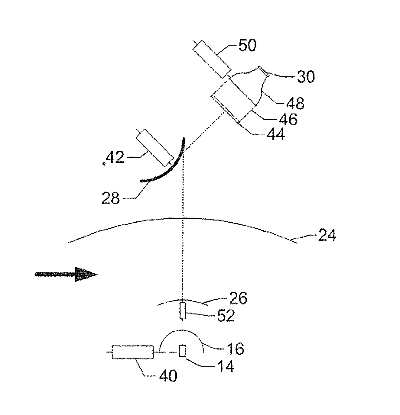
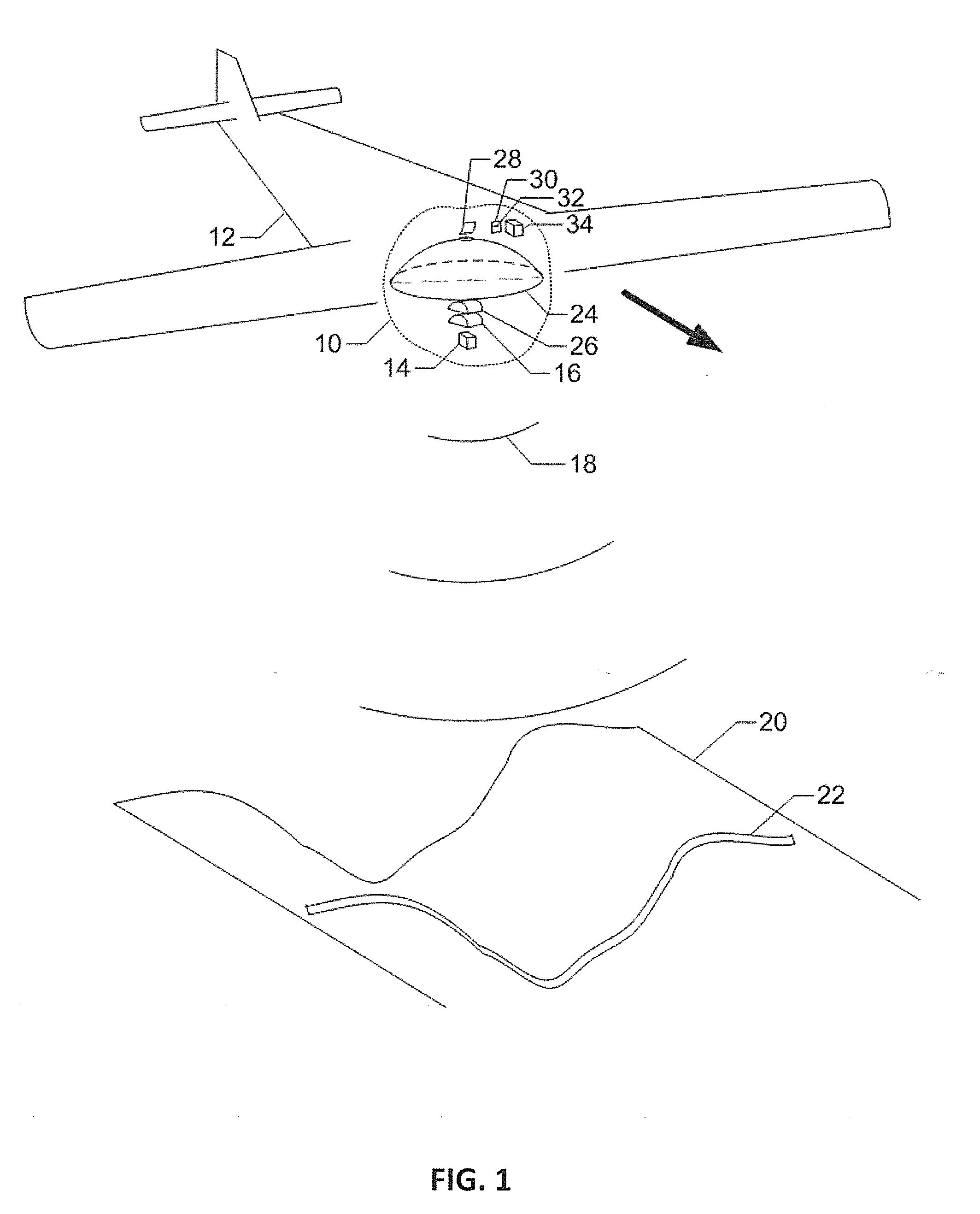
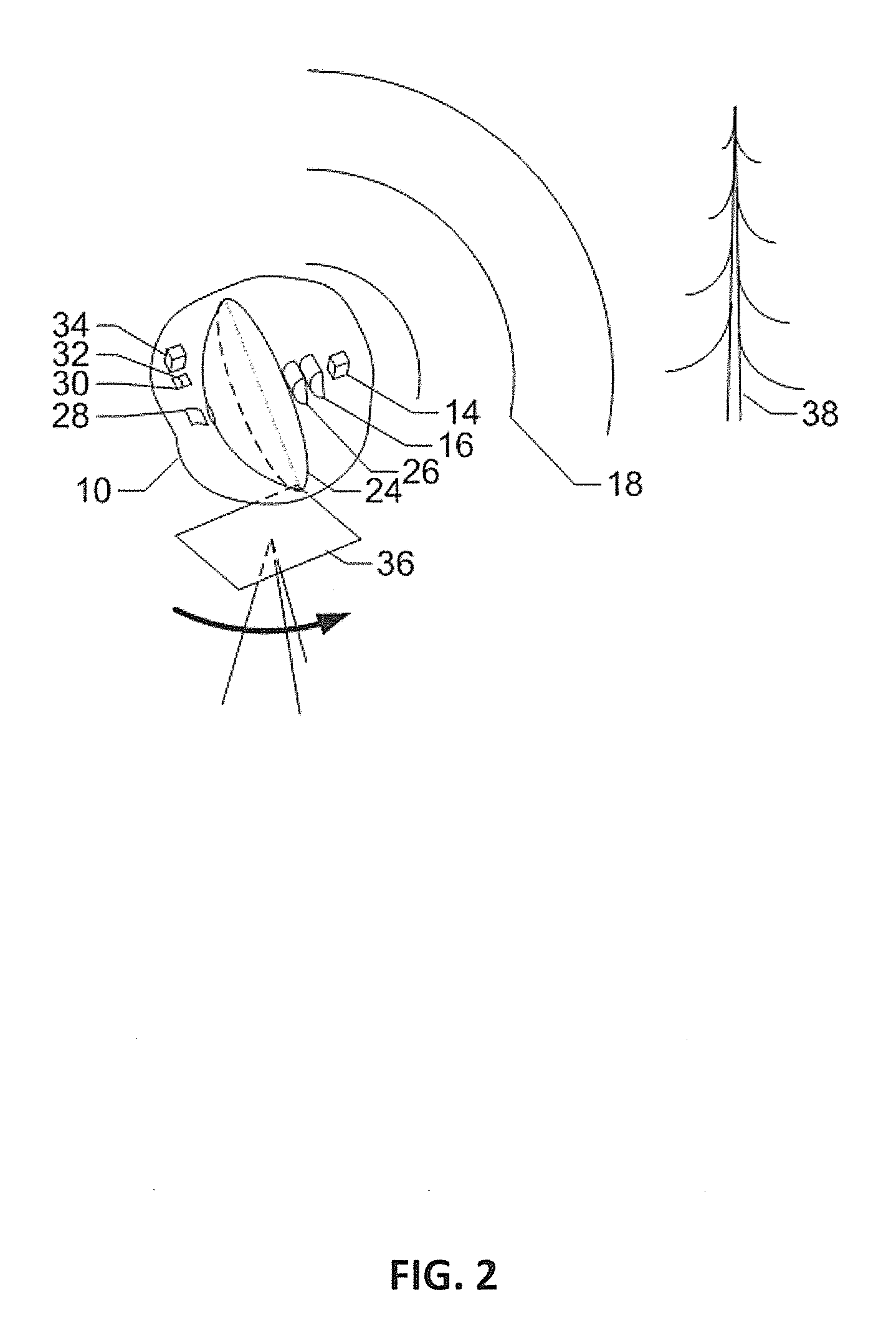
[0023]FIG. 1 is a perspective view of light ranging device 10 mounted on airborne platform 12. For convenience, at times herein the light ranging device may be referred to as a light ranger. The representation of airborne platform 12 is cut away to show light ranger 10 in more detail. Light from pulsed illumination source 14 is shaped by optics 16 into sheet of light 18 that propagates to a target 20. Light reflected from illuminated line 22 on target is collected by collection aperture 24 and focused by collection focusing optics 26 off displacement magnifier 28 onto sensor array 30 with the collection aperture, collection focusing optics, and displacement magnifier together providing an embodiment of what may be termed collection optics. An image on sensor array 32 is read out onto a processor 34, which may be configured, for example by program instructions or electronic circuitry to provide correction, a calculation, storage (for example in associated memory), or transmission (fo...


PUM


Abstract

A light ranging device is mounted on a moveable platform, for example an airplane. The light ranging device may include an illumination source for providing a pulse of light, beam shaping optics to form a beam of light directed at a target, and collection optics for providing reflected light of the beam to a light-sensitive sensor array. A processor may determine range to the target based on spatial displacement of received light on the sensor array compared to expected position of the light due to platform movement.

Description

CROSS-REFERENCE TO RELATED APPLICATION[0001]This application is a national phase filing, under 35 U.S.C. §371(c), of International Application No. PCT / US2013 / 040663, filed May 10, 2013, which claims the benefit of U.S. Provisional Application No. 61 / 646,284 filed on May 12, 2012, the disclosures of which are incorporated herein by reference in its entirety.BACKGROUND OF THE INVENTION[0002]This invention relates generally to non-contact measurement of distances or ranges using time-of-flight measurement of reflected pulses of light, and more particularly to such measurements with conversion of temporal variation of the reflections to spatial variation across an array of detectors.[0003]Different approaches to non-contact measurement of distances can be grouped into several major categories. Triangulation systems use a light source and detector (or two detectors for passive systems) separated by a baseline. The baseline and the paths of light form a triangle. Determination of an angle...

Claims


Application Information

Patent Timeline
IPC IPC(8): G01S17/08
CPCG01S17/08G01C15/002G01S17/10G01S17/89G01S17/933G01S17/931
Inventor VAN CRUYNINGEN, IZAK JAN
Owner VAN CRUYNINGEN IZAK JAN
Learn More