
Trunk injection needle

a needle and needle body technology, applied in the field of needles, can solve the problems of reducing the resistance of injecting drug liquid into the trunk, not easy to bend or break the needle, etc., and achieve the effect of not bursting the trunk, small resistance, and not easy to be bent or broken

Inactive Publication Date: 2016-12-15
NANJING FORESTRY UNIV
View PDF1 Cites 6 Cited by
  • Summary
  • Abstract
  • Description
  • Claims
  • Application Information

AI Technical Summary

Benefits of technology

The patent is for a trunk injection needle that is designed to have low resistance when moving in or out of the trunk, to be strong and resistant to bending or breaking, and to not damage the trunk.

Problems solved by technology

Therefore, at a position where the two outlet holes contact with the drug feeding hole, the wood bits are less or looser, which is more suitable for inputting the drug liquid into the trunk, and reduces a resistance for inputting the drug liquid into the trunk.
During withdrawing, forces at two sides of the needle are basically the same and will not be larger at one side, in such a manner that withdrawing from the trunk is easier, and it is not easy to bend or break the needle.

Method used


Image

  • Trunk injection needle
  • Trunk injection needle
  • Trunk injection needle

Examples


embodiment 1

Preferred Embodiment 1

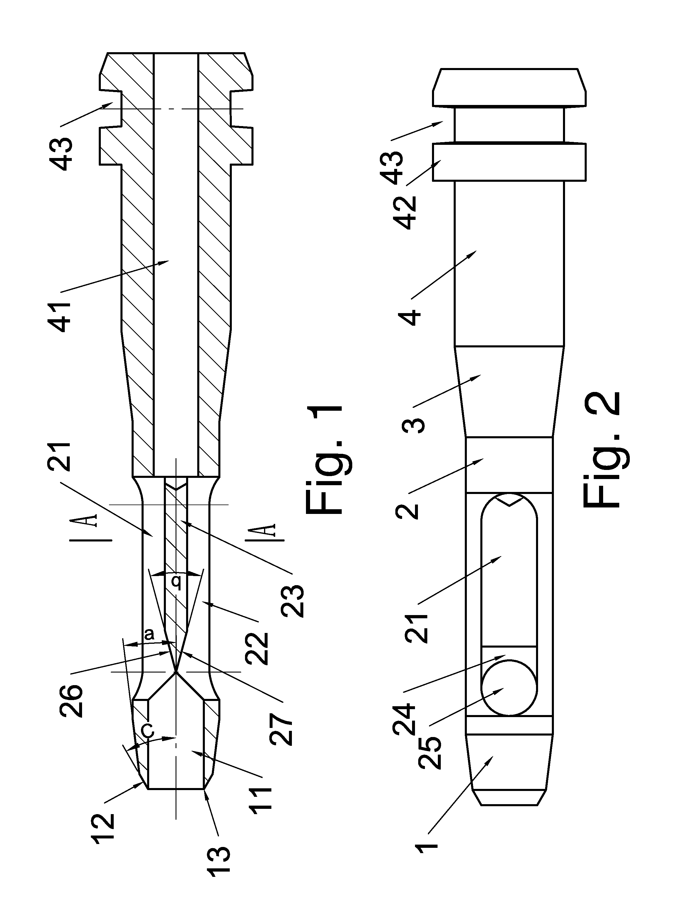
[0026]Referring to FIGS. 1-3, a trunk injection needle is provided, comprising: a front part 1 which is conical, a middle part 2 which is cylindrical, a cone transition part 3 and a rear part 4 which is cylindrical, which are respectively provided along a needle axis. A max outer diameter of the front part 1 which is conical equals to an outer diameter of the middle part 2 which is cylindrical. An outer diameter of the rear part 4 is larger than the outer diameter of the middle part 2 which is cylindrical, and the cone transition part 3 is provided between the middle part 2 which is cylindrical and the rear part 4 which is cylindrical.

[0027]The front part 1 has a bits guiding hole 11 extending along the needle axis, and the cone transition part 3 and the rear part 4 have a drug feeding hole 41 extending along the needle axis.

[0028]The middle part has two outlet holes 21 and 22 which are slotted and extend along a radical direction, and widths of the two outlet ...

embodiment 2

Preferred Embodiment 2

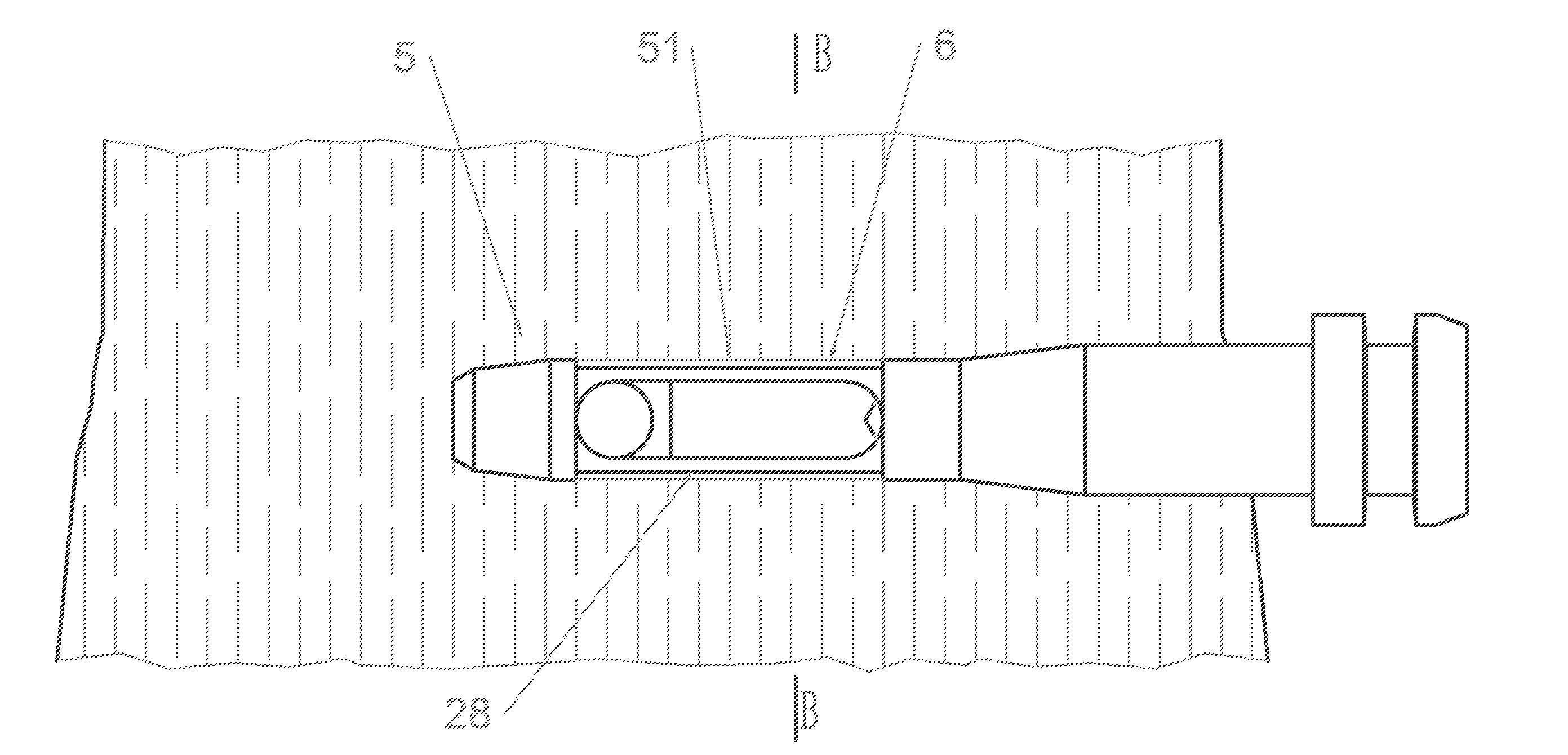
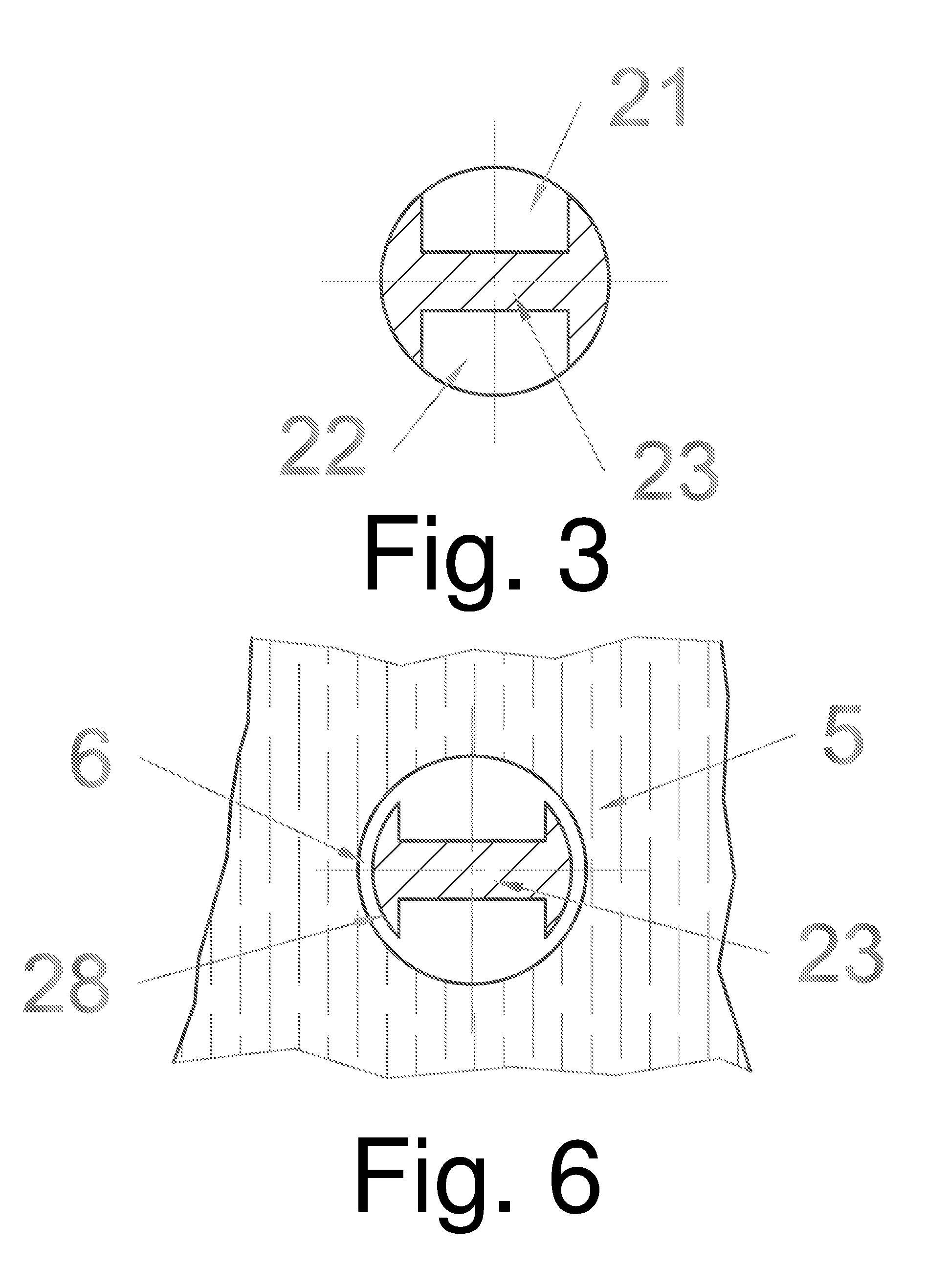
[0035]Referring to FIGS. 4-6, a trunk injection needle is provided. Differences between the preferred embodiment 1 and the preferred embodiment 2 are as follows. An outer diameter at a position 28 of the middle part 2, which has the two outlet slots 21 and 22, is smaller than outer diameters at other positions of the middle part 2, and also smaller than the max outer diameter of the front part 1 of the needle. Therefore, after a round hole 51 is pressed by a periphery of the front part 1 being conical, a size thereof is larger than the outer diameter of position 28 of the middle part 2 of the needle where the two outlet holes 21 and 22 are located, and an annular gap 6 is formed between a periphery the middle part 2 of the needle with the two outlet holes 21 and 22 and the round hole 51 on the trunk. Other structures of the preferred embodiment 2 are identical to that of the preferred embodiment 1.

[0036]According to the preferred embodiments 1 and 2, a needle s...


PUM


Abstract

A trunk injection needle includes: a front part which is conical, a middle part which is cylindrical, and a rear part which is cylindrical, which are respectively provided along a needle axis; wherein an outer diameter of the rear part is larger than outer diameters of the front part and the middle part; the front part has a bits guiding hole extending along the needle axis, and the rear part has a drug feeding hole extending along the needle axis; wherein the middle part has two outlet holes extending along a radical direction, and a separating board is provided between the two outlet holes; a rear end of the bits guiding hole communicates with the two outlet holes at two sides of the separating board; and a front end of the drug feeding hole communicates with the two outlet holes.

Description

CROSS REFERENCE OF RELATED APPLICATION[0001]This is a U.S. National Stage under 35 U.S.C 371 of the International Application PCT / CN2015 / 083621, filed Jul. 8, 2015, which claims priority under 35 U.S.C. 119(a-d) to CN 2014102236786, filed May. 23, 2014.BACKGROUND OF THE PRESENT INVENTION[0002]Field of Invention[0003]The present invention relates to a needle used during tree injecting administration.[0004]Description of Related Arts[0005]China lacks forest resources. Due to long-term excessive logging, available forest resources, which are already limited, are drastically reduced. In recent decades, with deteriorating environment and rapid growth of forest pests, trees suffer from wide spread infestation, leading to a low survival rate. Forestry pests, such as stem borer, Gidding insects, Anoplophora nobilis, Shecia siningensis Hsu, and sucking pests with wax protective shells, are rapidly spread.[0006]Conventional spray methods for controlling pests have the following problems: duri...

Claims


Application Information

Patent Timeline
Patent Type & Authority Applications(United States)
IPC IPC(8): A01G7/06A01G23/00
CPCA01G23/00A01G7/06A01G29/00
Inventor SHANG, QINGQINGYIN, TONGMINGSUN, ZHIWUJU, YUNWEI
Owner NANJING FORESTRY UNIV
Learn More