Ultrasonic image pickup device and method

a pickup device and ultrasonic imaging technology, applied in ultrasonic/sonic/infrasonic image/data processing, tomography, applications, etc., can solve the problems of not being able to obtain blood flow information in a flowing field, not being able to display a flowing direction, not being able to obtain blood flow pressure field,

Inactive Publication Date: 2016-12-15
HITACHI LTD
View PDF9 Cites 24 Cited by
  • Summary
  • Abstract
  • Description
  • Claims
  • Application Information

AI Technical Summary

Benefits of technology

[0008]According to the present invention, diagnostic information is provi

Problems solved by technology

It is not possible to display a flowing direction, that is, in which direction the blood is flowing in a tomographic plane.
Therefore, in the VFM, it is not possible to obtain blood flow information in a flowing field like an actual blood that passes through the imaging area.
For exam

Method used


Image

  • Ultrasonic image pickup device and method
  • Ultrasonic image pickup device and method
  • Ultrasonic image pickup device and method

Examples


first embodiment

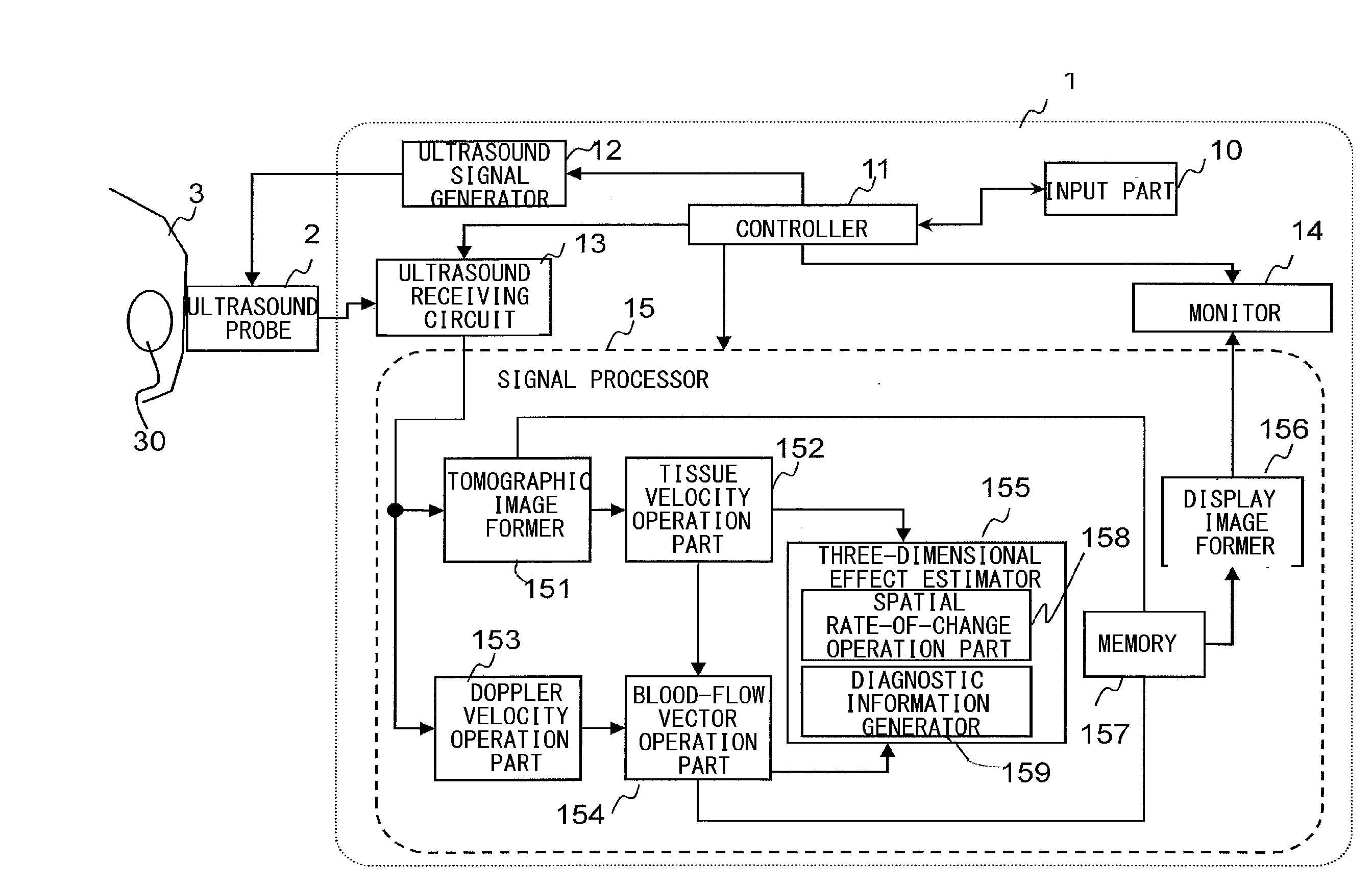
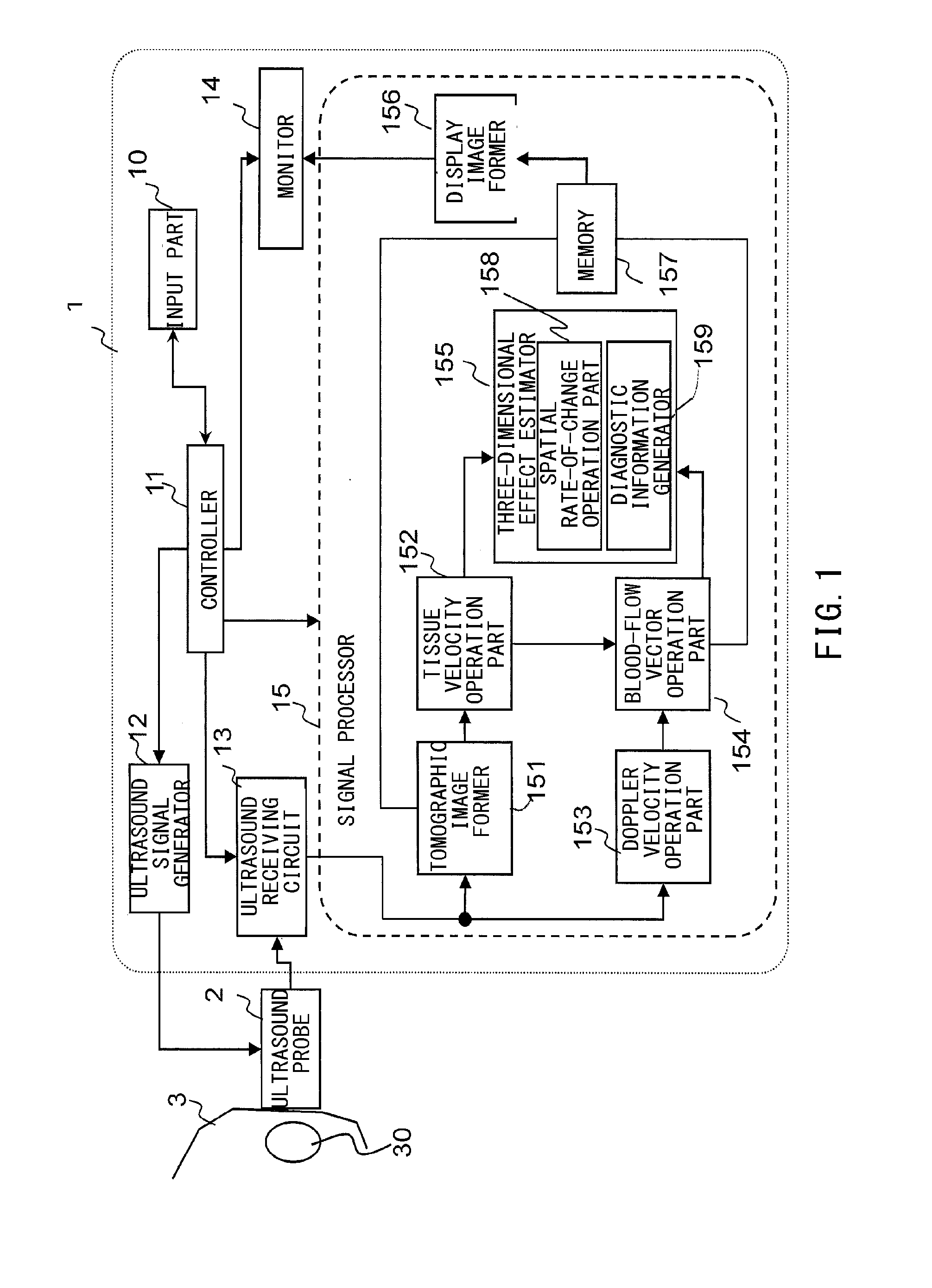
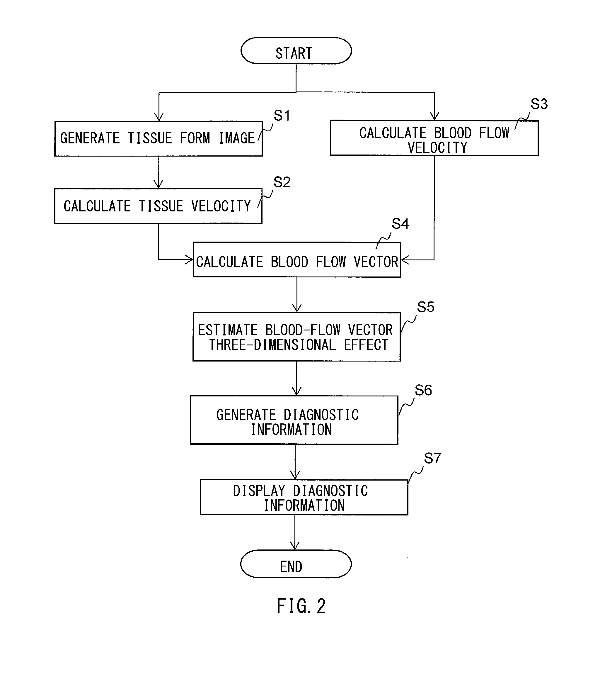
[0040]The first embodiment will be described with reference to a processing flowchart as shown in FIG. 2. With reference to FIG. 2, there will be described, as a specific example, the case where a radiation region 30 (FIG. 1) indicates a portion including the left ventricle. However, the radiation region 30 may be a blood vessel or another heart chamber desired by an examiner.

[0041]As shown in FIG. 2, in the present embodiment, following processes are performed; the process of forming a tissue form image and calculating a tissue velocity (S1, S2), a process of calculating a blood flow velocity (S3), a process of calculating a blood flow vector by using the tissue velocity and the blood flow velocity (S4), a process of estimating a three-dimensional effect of the blood flow vector by using the blood flow vector (blood flow velocity) calculated by two methods (S5), a process of generating diagnostic information by using thus estimated three-dimensional effect (S6), and the process of ...

second embodiment

[0106]The present embodiment is similar to the first embodiment, having the following processes; a process of calculating a blood flow velocity from echo signals by two methods, with regard to an identical position, a process of evaluating consistency of the blood flow velocities calculated by the two methods, a process of estimating three-dimensional effect of the blood flow in an imaging area, by using the consistency of the blood flow velocities, and a process of generating diagnostic information such as a pressure gradient between two points, a blood flow flux, and a tissue blood-flow interaction force, by using the three-dimensional effect of the blood flow being estimated.

[0107]The present embodiment features that the aforementioned processes are performed in each time phase, or in characteristic phases such as a contracting phase and a diastolic phase, by using cardiac cycle information inputted from the input unit 10 and image information obtained from a tomographic image fo...


PUM


Abstract

Provided is an ultrasound imaging apparatus that is cable of estimating a three-dimensional effect of a blood flow, by using blood-flow velocity information obtained by a color Doppler method, and presenting diagnostic information into which the three-dimensional effect is reflected. The ultrasound imaging apparatus of the present invention is provided with an ultrasound probe configured to transmit ultrasound waves to a test object and to receive echo signals reflected from the test object, and a signal processor configured to process the echo signals received by the ultrasound probe, and the signal processor estimates the three-dimensional effect of the blood flow velocity, from a difference between a first blood flow velocity estimated from the echo signals by a first method, and a second blood flow velocity estimated by a second method which is different from the first method, and generates diagnostic information into which the three-dimensional effect is reflected.

Description

TECHNICAL FIELD[0001]The present invention relates to an ultrasound imaging apparatus for medical use, and more particularly, to an ultrasound imaging apparatus being capable of estimating a velocity vector of a blood flow, on the basis of information according to the color Doppler method, with a function to estimate a three-dimensional effect of the blood flow velocity.BACKGROUND ART[0002]According to the color Doppler method, it is only a velocity component in an ultrasound beam direction that can be measured directly. It is not possible to display a flowing direction, that is, in which direction the blood is flowing in a tomographic plane. A method (Vector Flow Mapping: VFM) is suggested, accordingly, where velocity components in an ultrasound beam direction and a direction orthogonal thereto are estimated, using a velocity on a boundary between tissues and the mass conservation law of a two-dimensional flow, and a velocity vector is obtained from the velocity components in the u...

Claims


Application Information

Patent Timeline
IPC IPC(8): A61B8/06A61B8/00A61B8/08A61B5/0402A61B8/14
CPCA61B8/06A61B5/0402A61B8/14A61B8/488A61B8/463A61B8/483A61B8/5207A61B8/0883A61B8/5246A61B5/318
Inventor TANAKA, TOMOHIKOOKADA, TAKASHI
Owner HITACHI LTD
Why Eureka
Try Eureka