Vehicle body component, manufacturing device of the same, and manufacturing method for the same

a technology for vehicle body parts and manufacturing devices, which is applied in the direction of superstructures, transportation and packaging, other domestic articles, etc., can solve the problems of joining loss at the joined section, and achieve the effects of preventing unnecessary buckling improving the rigidity of the bent portion, and increasing the pressure on the one side portion of the metal plate by the movable di

Active Publication Date: 2016-12-15
TOYOTA JIDOSHA KK
View PDF3 Cites 3 Cited by
  • Summary
  • Abstract
  • Description
  • Claims
  • Application Information

AI Technical Summary

Benefits of technology

[0044]In the manufacturing method for a vehicle body component, as described above, when the movable die pressurizes the one side portion of the metal plate to the bent portion side, the portion of the metal plate is likely to move to the first gap by the plastic flow, the first gap being positioned on the outer side in the bent radial direction of the bent portion. After the portion of the metal plate moves to this first gap by the plastic flow, the pressure on the one side portion of the metal plate by the movable die is increased. In this way, the portion of the metal plate can move favorably to the second gap by the plastic flow, the second gap being positioned on the inner side in the bent radial direction of the bent portion (on the side to which the portion of the metal plate is less likely to move by the plastic flow).
[0045]In other words, in the present invention, in the initial period that the movable die starts pressurizin

Problems solved by technology

However, joining loss occurs at a joined section between the outer peripheral bent portion

Method used


Image

  • Vehicle body component, manufacturing device of the same, and manufacturing method for the same
  • Vehicle body component, manufacturing device of the same, and manufacturing method for the same
  • Vehicle body component, manufacturing device of the same, and manufacturing method for the same

Examples


first embodiment

[0071]A description will be made on a vehicle body component 10, a manufacturing device of a vehicle body component 12, and a manufacturing method for a vehicle body component according to a first embodiment of the present invention on the basis of FIG. 1 to FIG. 5.

[0072](Manufacturing Device and Manufacturing Method)

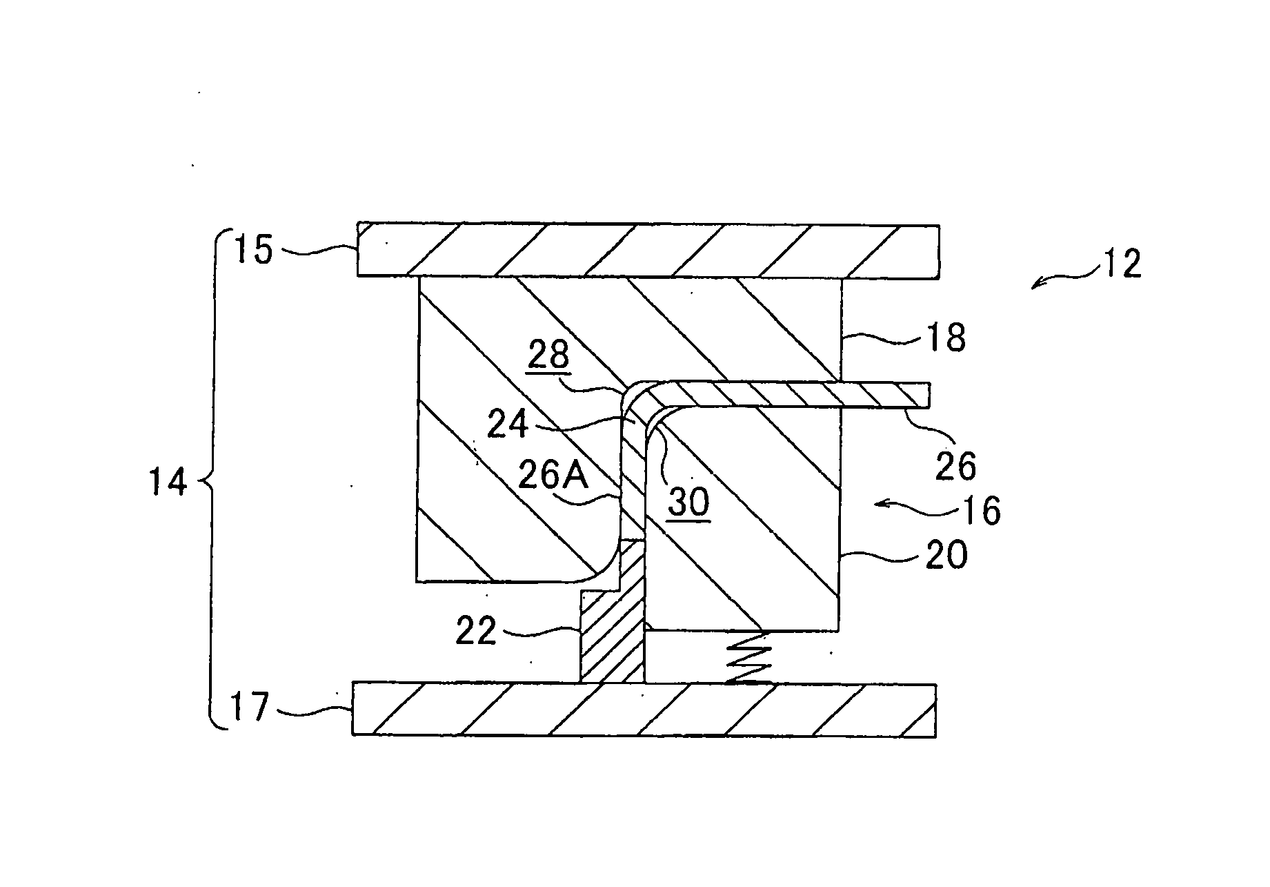
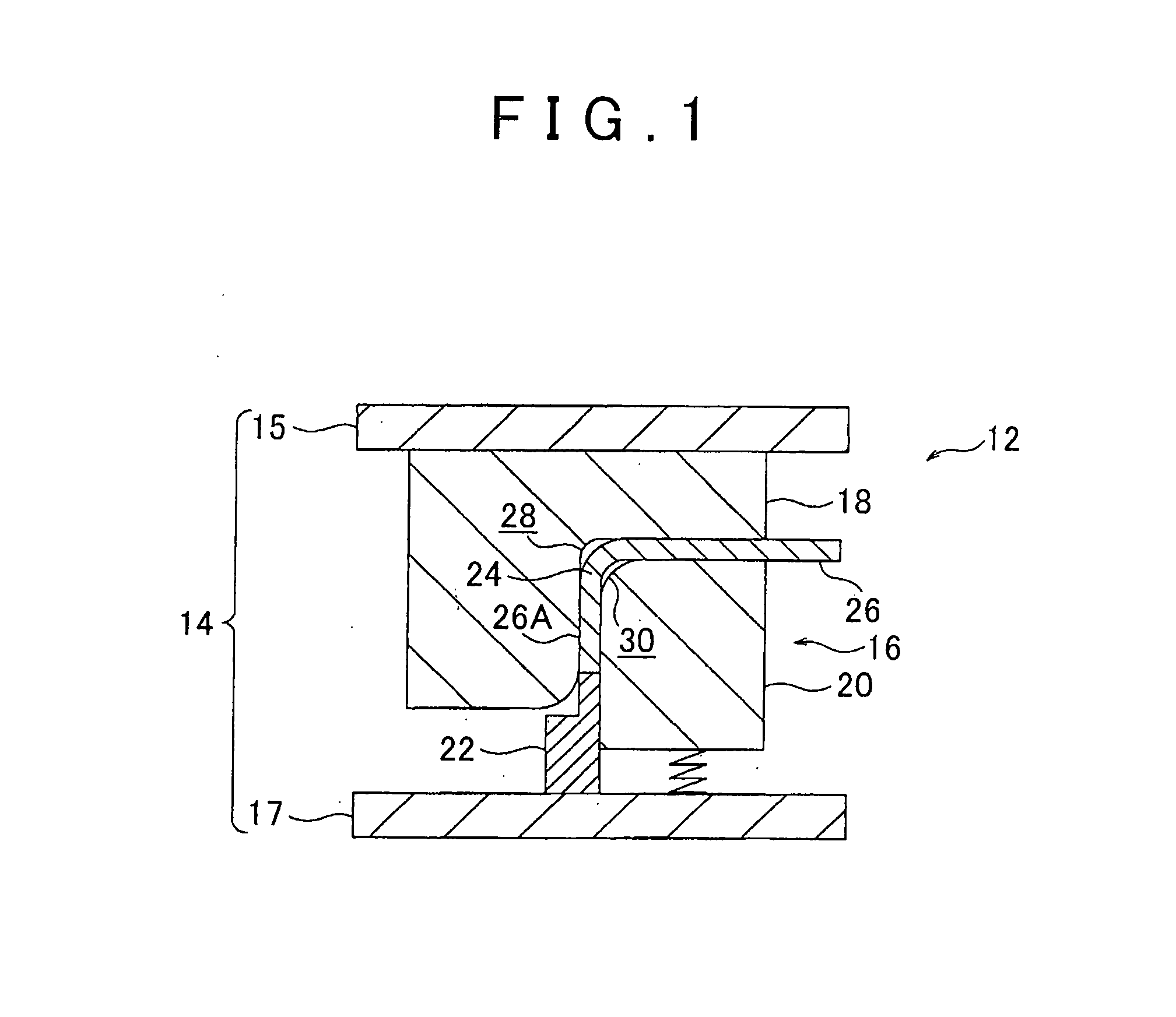
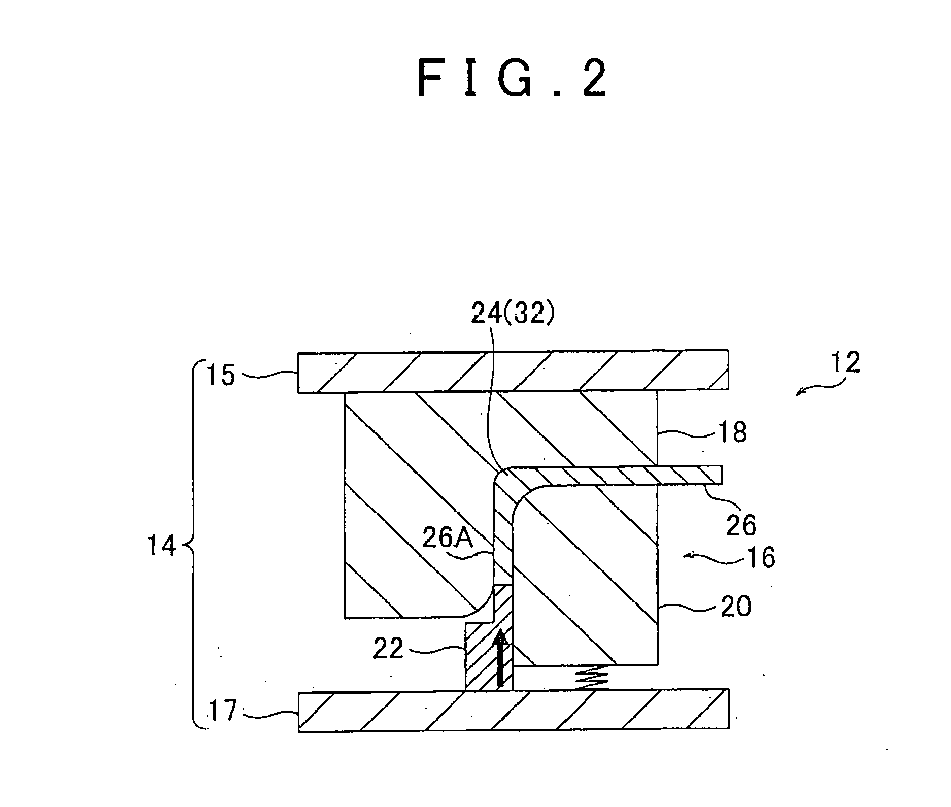
[0073]First, the manufacturing device of a vehicle body component 12 (hereinafter, simply referred to as the manufacturing device 12), which is shown in FIG. 1 and FIG. 2, will be described. This manufacturing device 12 is a device for manufacturing the vehicle body component according to this embodiment by using the manufacturing method for the vehicle body component according to this embodiment. This manufacturing device 12 is a device that performs coining, and is configured by including a press machine 14 as a device main body and a press die 16 that is attached to the press machine 14. Noted that the press machine 14 and the press die 16 are schematically illustrat...

second embodiment

[0097]FIG. 6 is a cross-sectional view of a partial configuration of a press die 62 in a manufacturing device of a vehicle body component 60 according to a second embodiment of the present invention. This manufacturing device 60 is a device that carries out a manufacturing method for the vehicle body component according to this second embodiment, and the press die 62 has basically the same configuration as the press die 16 according to the first embodiment. However, in this press die 62, a width dimension W1 of the first gap 28 that is along the bent radial direction of the bent portion 24 is set to be larger than a width dimension W2 of the second gap 30 that is along the bent radial direction of the bent portion 24. Except for what is just described, the configuration of the second embodiment is the same as that of the first embodiment.

[0098]Here, when the press machine 14 uses the movable die 22 (both of which are not shown in FIG. 6) to pressurize the one side portion 26A, which...

third embodiment

[0099]FIG. 7A is a cross-sectional view of an initial state of the metal plate 26 at beginning of pressurization by a manufacturing device of a vehicle body component 70 according to a third embodiment of the present invention. This manufacturing device 70 is a device that carries out a manufacturing method for the vehicle body component according to this third embodiment, and basically has the same configuration as the manufacturing device 12 according to the first embodiment. However, this manufacturing device 70 includes a load sensor 72 for detecting a reactive force that is received by the movable die 22 (for outputting a signal that corresponds to the reactive force) during the pressurization of the one side portion 26A of the metal plate 26. This load sensor 72 is electrically connected to a controller 74 that controls actuation of the press machine 14 (which is not shown in FIG. 7A, FIG. 8A, FIG. 9A).

[0100]The controller 74 is configured to increase a pressure on the one sid...


PUM

PropertyMeasurementUnit
Thicknessaaaaaaaaaa
Pressureaaaaaaaaaa
Shapeaaaaaaaaaa

Abstract

In a vehicle body component, a bent portion that is formed in a component main body made of a metal plate is formed of a thickened portion, in which a plate thickness of the metal plate as a material of the component main body is gradually increased. Just as described, since the bent portion, on which stress is likely to be concentrated when a load is applied to the component main body, is formed of the thickened portion, a plate thickness of a portion where the stress is not concentrated can be prevented from being increased more than necessary. This can contribute to improvement of mass efficiency.

Description

BACKGROUND OF THE INVENTION[0001]1. Field of the Invention[0002]The present invention relates to a component that constitutes a vehicle body such as an automobile, a manufacturing device of the same, and a manufacturing method for the same.[0003]2. Description of Related Art[0004]In a vehicle body front structure that is described in Japanese Patent Application Publication No. 10-316026 (JP 10-316026 A) below, a horizontal surface provided at an upper end of a front suspension tower is provided with a front spring support plate (hereinafter referred to as a suspension tower plate). An outer periphery of this suspension tower plate is bent to incline downward. The outer periphery (an outer peripheral bent portion) overlaps a lower surface of an upper end bent portion of the front suspension tower, and is joined to the lower surface by welding or the like. An upper end of a front suspension is fastened and fixed to this suspension tower plate.[0005]In the vehicle body front structure,...

Claims


Application Information

Patent Timeline
IPC IPC(8): B21D35/00B21D53/88
CPCB21D53/88B21D35/006B21D22/06B21J5/08B21K23/00B62D25/00B21D35/00
Inventor KOSAKA, NAOYAASADACHI, HIDEKIYAMAGUCHI, TAICHI
Owner TOYOTA JIDOSHA KK
Why Eureka
Try Eureka