Control system

a control system and control system technology, applied in the direction of electric control, combustion engines, machines/engines, etc., can solve the problems of engine stall, difficult to maintain a good combustion state, and the accurate abnormal diagnosis of the fuel pressure sensor takes some time, so as to restrain the deterioration of the combustion state and the deterioration of the combustion engin

Active Publication Date: 2016-12-15
TOYOTA JIDOSHA KK
View PDF11 Cites 5 Cited by
  • Summary
  • Abstract
  • Description
  • Claims
  • Application Information

AI Technical Summary

Benefits of technology

[0013]When the temporary abnormality is determined, the electronic control unit performs an injection control on the fuel injection valve so as to perform a fuel injection without performing the partial lift injection. That is, even in a case where it is difficult to confirm that an abnormality occurs in the fuel pressure sensor, when its occurrence is suspected, the electronic control unit prohibits the partial lift injection. Accordingly, even when it takes time to make an abnormality determination of the fuel pressure sensor, deterioration in the combustion state is restrained. This accordingly makes it possible to secure the abnormality diagnosis accuracy of the fuel pressure sensor and to restrain the deterioration in combustion of the engine during the diagnosis.
[0014]Note that, in the engine including, as the fuel pump, a high-pressure fuel pump that pressurizes a fuel pumped up by a feed pump from a fuel tank and supplies the fuel to the fuel injection valve, the electronic control unit controls an operation of the high-pressure fuel pump based on the detection value of the fuel pressure sensor such that the detection value of the fuel pressure sensor achieves a target fuel pressure set according to the engine operation state. In such a control system, it is possible to perform the fa...

Problems solved by technology

As a result, a combustion state of the engine deteriorates, which may cause a misfire or an engine stall.
However, an accurate abnormality diagnosis of the fuel pressure sensor takes some time.
Further, in a case where the combustion state of the engine is secured by the partial lift injection, when a deviation occurs in the injection amount of the partial lift injection, it is hard to maintain a good combustion state.
Accordingly, in a case where an abnormality occurs in the fuel pressure sensor at a time when the p...

Method used


Image

  • Control system
  • Control system
  • Control system

Examples


Embodiment Construction

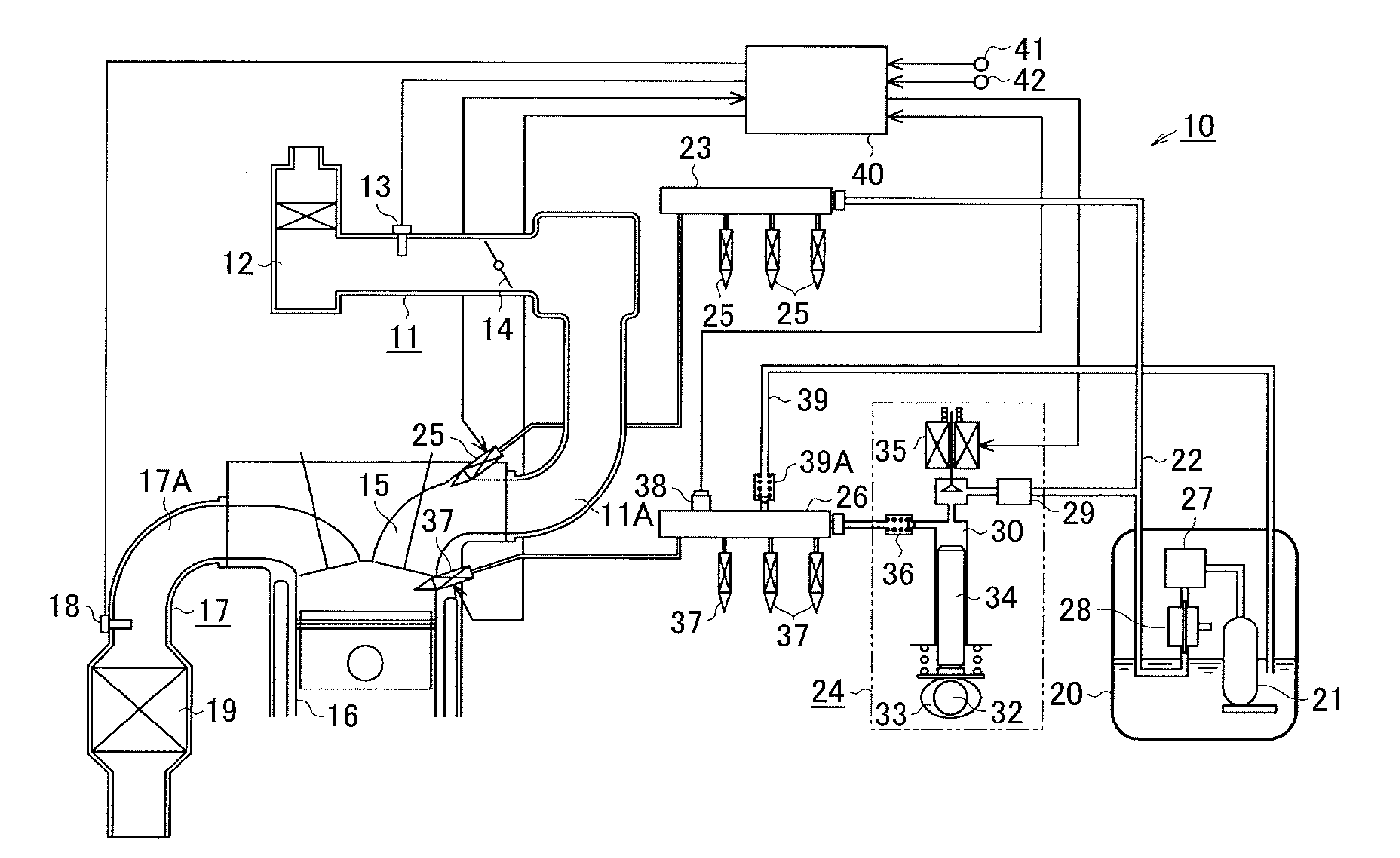
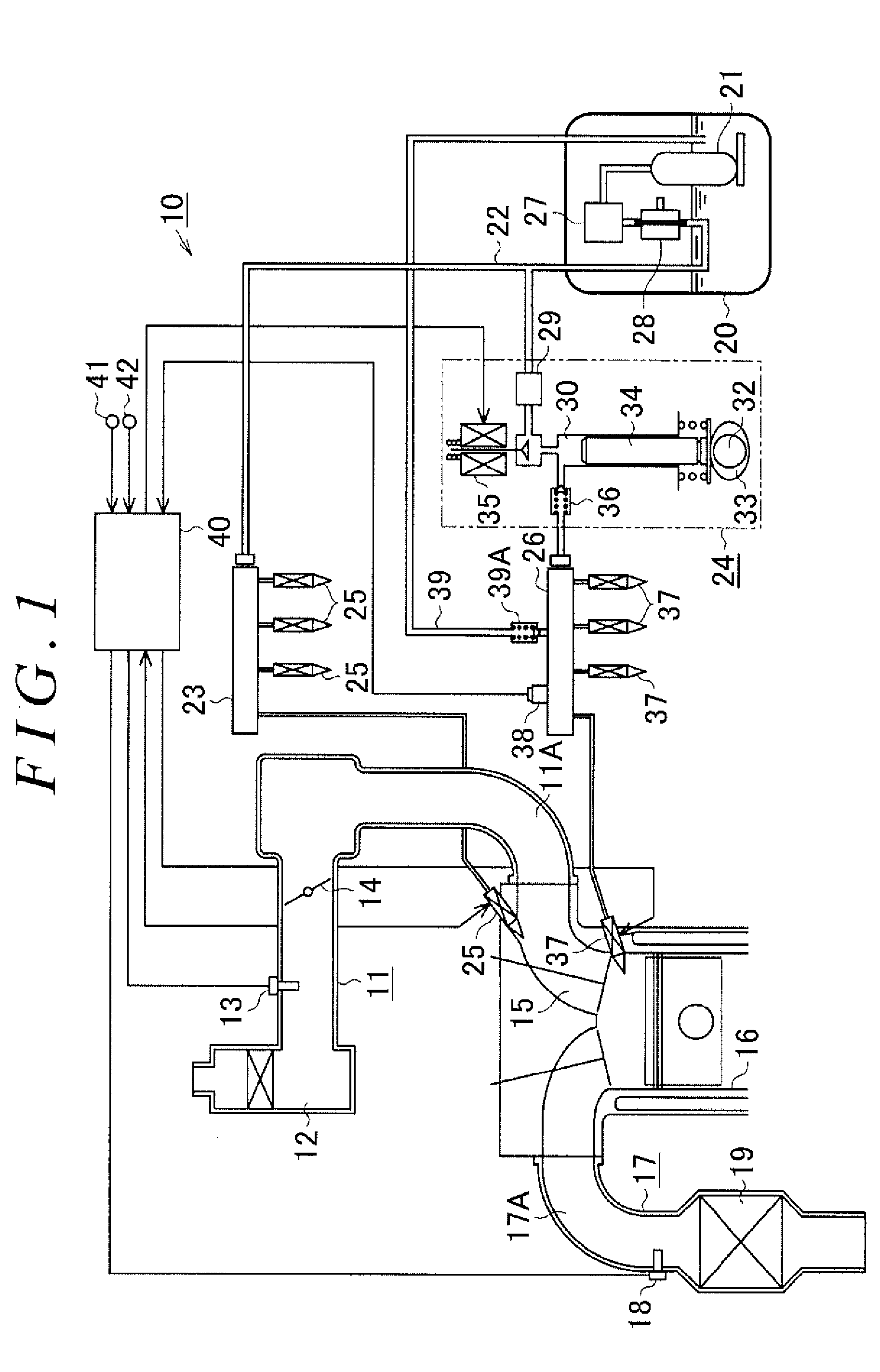
[0032]The following describes details of a first embodiment of a control system with reference to FIG. 1 to FIG. 6. As illustrated in FIG. 1, an intake passage 11 of an engine 10 to which the control system of the present embodiment is applied is provided with an air cleaner 12, an air flow meter 13, a throttle valve 14, and an induction manifold 11A in order from an upstream side. The air cleaner 12 filters out dust form intake air flowing into the intake passage 11. The air flow meter 13 detects a flow rate (an intake-air amount GA) of the intake air. The throttle valve 14 adjusts the intake-air amount by changing a valve opening degree thereof. The intake passage 11 is branched off at the induction manifold 11A, and then connected to each cylinder 16 through an intake port 15 provided for each cylinder.

[0033]In the meantime, an exhaust passage 17 of the engine 10 is provided with an exhaust manifold 17A, an air / fuel-ratio sensor 18, and a catalyst device 19 in order from the upst...


PUM


Abstract

An abnormality flag is set when a first abnormality determination condition is established in an abnormality diagnosis of a fuel pressure sensor and it is determined that an abnormality occurs. In a case where the abnormality flag is kept cleared, when a fuel pressure detection value of the fuel pressure sensor is kept fixed for a prescribed time T2 or more and a second abnormality determination condition is established, a partial lift injection is prohibited, such that an injection control of a fuel injection valve is performed so as to perform a fuel injection without performing the partial lift injection.

Description

INCORPORATION BY REFERENCE[0001]The disclosure of Japanese Patent Application No. 2015-118672 and 2016-082165 filed on Jun. 11, 2015 and Apr. 15, 2016 including the specification, drawings and abstract is incorporated herein by reference in its entirety.BACKGROUND OF THE INVENTION1. Field of the Invention[0002]The present invention relates to a control system.2. Description of Related Art[0003]An electromagnetic fuel injection valve provided in an engine to be provided in a vehicle or the like is configured such that a valve body is opened by current application to a built-in electromagnetic solenoid so as to inject a fuel. Further, in an engine of a cylinder injection type or the like, a fuel pumped up by a feed pump from a fuel tank is pressurized by a high-pressure fuel pump so as to be supplied to a fuel injection valve. In such an engine, an injection amount of the fuel injection valve per current application time changes depending on a pressure (a fuel pressure) of the fuel to...

Claims


Application Information

Patent Timeline
IPC IPC(8): F02D41/22F02D41/30F02D41/40
CPCF02D41/222F02D2041/223F02D41/3094F02D41/40F02D41/1475F02D41/3082F02D41/402F02D41/0255F02D41/08F02D41/1454F02D41/20F02D41/3845F02D2041/227F02D2200/0602Y02T10/40
Inventor NAKANO, TOMOHIRO
Owner TOYOTA JIDOSHA KK
Why Eureka
Try Eureka