Systems and methods for detecting wear of brake pads

a technology of brake pads and sensors, applied in the field of vehicle brake pads, can solve the problems of brake pads becoming thinner, requiring replacement, and occupants' danger, and achieve the effect of reducing the electrical conductivity measured by the conductive filamen

Inactive Publication Date: 2016-12-15
EDEN GIDEON
View PDF8 Cites 16 Cited by
  • Summary
  • Abstract
  • Description
  • Claims
  • Application Information

AI Technical Summary

Benefits of technology

[0014]The sensor can include an electrically conductive filament embedded in the brake pad at a predetermined distance with respect to a brake pad surface that contacts the rotating portion of the wheel. The electrical conductivity as measured by the conductive filament can decrease when the brake pad is worn to at least the predetermined location.
[0031]The sensor can comprise an electrically conductive filament embedded in the brake pad at a predetermined distance with respect to a brake pad surface that contacts the rotating portion of the wheel. Accordingly, electrical conductivity measured by the conductive filament decreases when the brake pad is worn to at least the predetermined location.

Problems solved by technology

Failure to periodically perform this inspection can result in accidents due to brake malfunctions, which can result in danger to vehicle occupants and costly repairs to the vehicle.
As time progresses, the brake pads can become thinner and may need to be replaced.
Consequently, the brake pad can totally wear out and the hard metal pad carriers (also called pad holders) can come in contact with the rotor causing substantial damage and creating dangerous and inefficient braking of the vehicle.
There are several disadvantages of these systems, namely, undue false positives indicating to the vehicle operator to replace the brake pads.
Car manufacturers may incur substantial liability for any false negative occurrences.
In other words, if the brake pad is in need of replacement and the system does not generate an alarm, and a consequent accident occurs, the manufacturer may be responsible due to the fact that no alarm was generated.
Consequently, the sensors and associated alarm indications may be designed to be overly sensitive to avoid the false negative scenario.
Even still, a rupture in the wires connecting the sensor to the dashboard can also produce an alarm not related to the actual condition of the brake pad.
This false positive indication can become so frequent and so disturbing to vehicle operators, that many operators may neutralize or deactivate the system entirely, thereby defeating the whole purpose of the system.
Another disadvantage to the “dashboard approach” is that it does not typically provide specific information about which brake pad needs to be replaced.
Because brake pads may wear at different rates, the operator will still have to remove all the wheels to determine which pad is in need of maintenance.
For vehicles, such as large trucks with many wheels, in which removal of wheels is costly and labor intensive, the dashboard approach can provide little value.

Method used


Image

  • Systems and methods for detecting wear of brake pads
  • Systems and methods for detecting wear of brake pads
  • Systems and methods for detecting wear of brake pads

Examples


resistivity brake pad embodiments

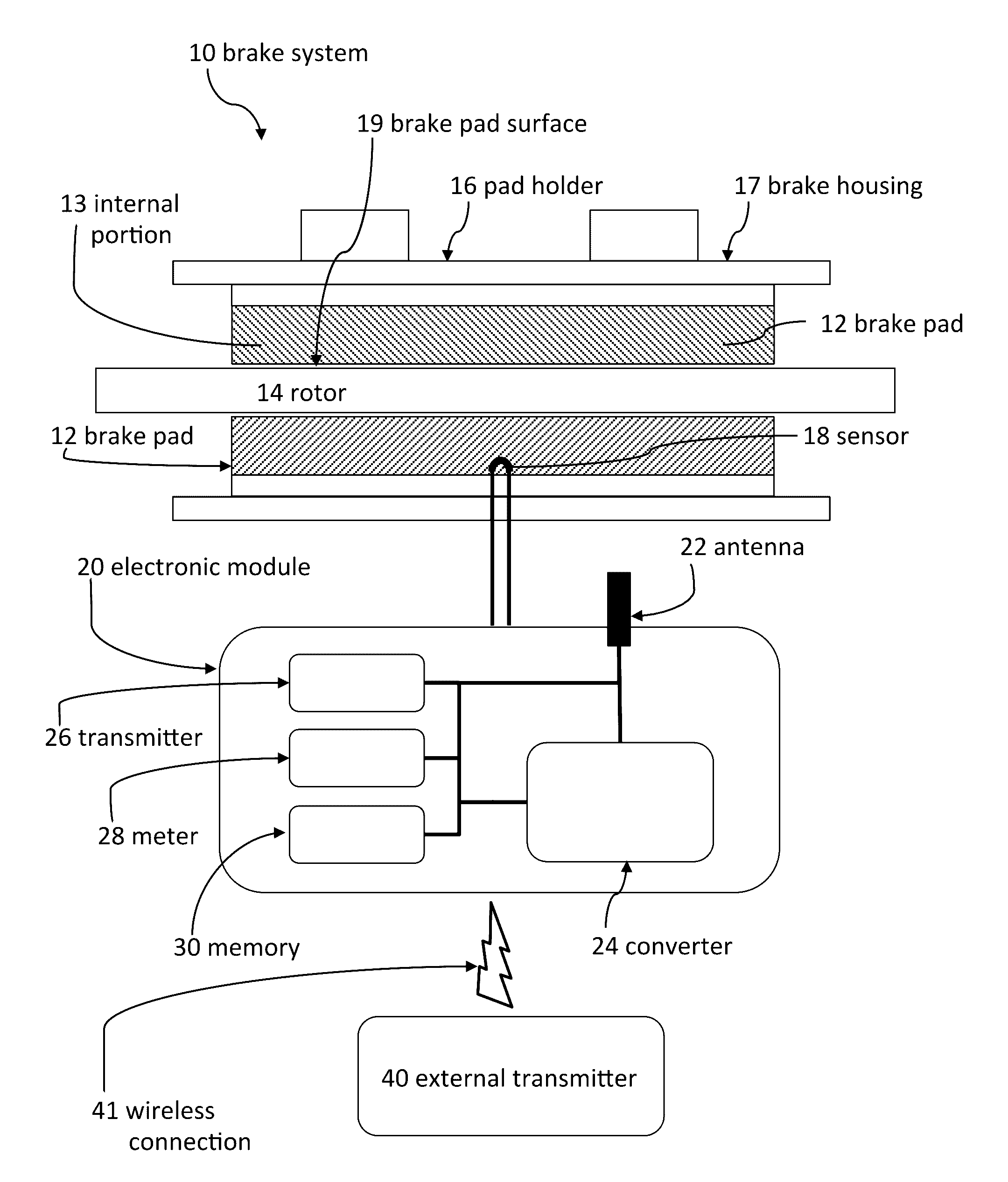
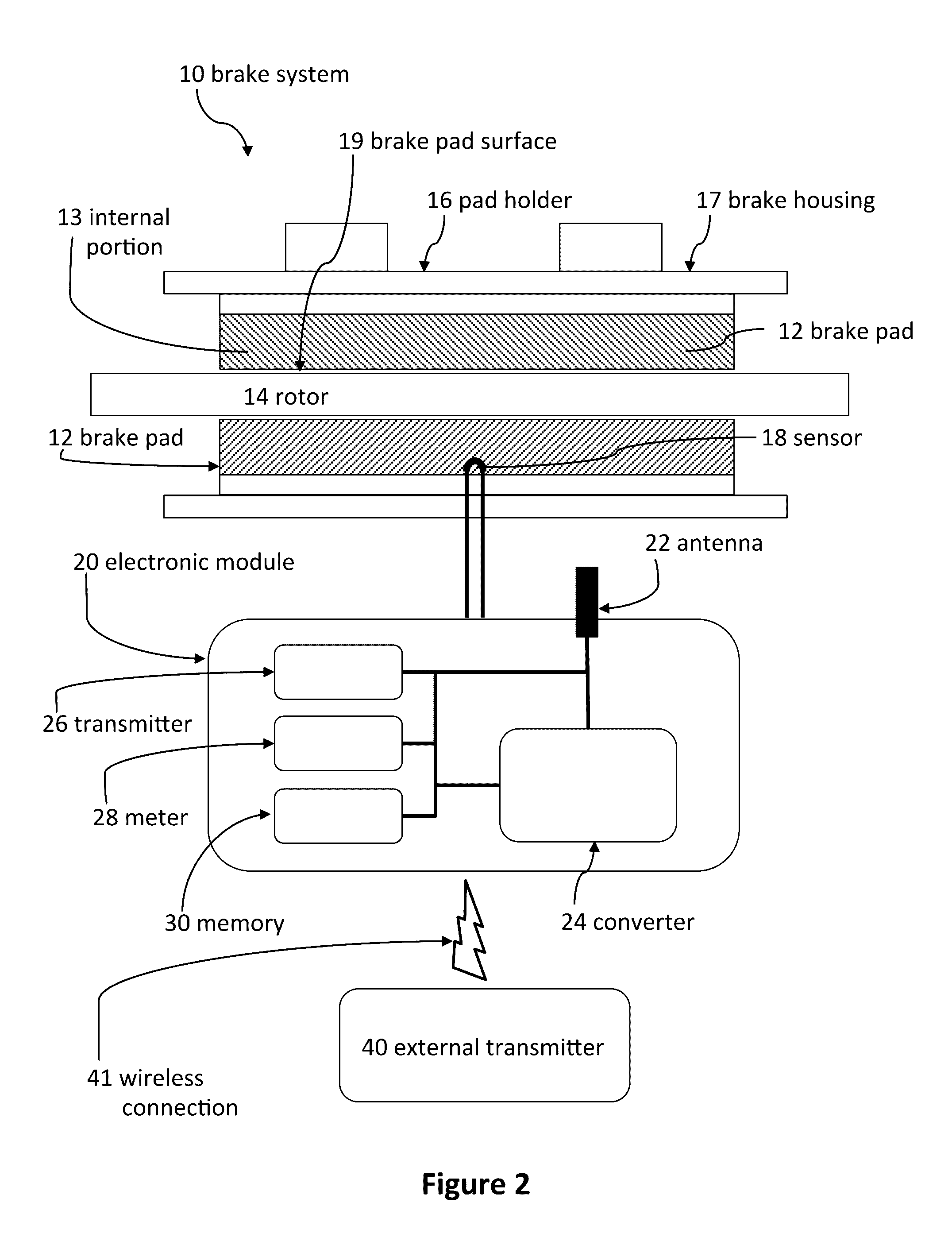
[0090]With reference to FIG. 4, a brake system 10 can include brake pads 12 that are configured to detect electrical properties of the brake pad 12, which can indicate the thickness of an internal portion 13 of the brake pad 12. Accordingly, a traditional brake pad can be replaced by a brake pad 12 that is at least partially conductive to electrical current. In this manner, the inner portion 13 of the brake pad 12 can be doped with electrically conductive material. Therefore, the inner portion 13 may have a combination of ceramic (non-conductive material)and conductive material (as doped throughout). The combination of materials can thereby convert the inner portion 13 of the brake pad 12 into an electrical resistor with a resistivity (inversely) related to the thickness of the inner portion 13.

[0091]Accordingly, the electrical resistivity of the brake pad 12 can be periodically or continuously measured by embedded electronic circuitry, such as a meter 28 coupled to sensors 18, such...

battery embodiments

[0106]Embodiments of the brake system 10 can include an internal battery 46to provide supply energy to the components of the electronic module 20. In some embodiments, the battery 46 is provided in lieu of the energy converter 24. In such embodiments, no radio frequency energy is sent from an external transmitter 40. Consequently the energy converter 24 can be eliminated from the electronic module 20 because the internal battery 46 is used to energize all the electronic components. However, in some embodiments, the battery 46 is provided in addition to the energy converter 24, as previously disclosed. In such embodiments, the components can be energized via supply energy from the battery 46 and / or the energy converter 24. In addition, the energy converter can be used periodically to charge the battery. The battery 46 can be located at any location within or along the vehicle, such as adjacent to the brake pad, adjacent to the wheel well, and the like. In some embodiments the vehicle...


PUM


Abstract

A system can be used to indicate wear of a brake pad. The system can include a brake housing, a brake pad mechanically coupled to the brake housing, and a sensor mechanically coupled to the brake pad. The sensor can determine when the brake pad has been worn to a predetermined location. The system can also include an electronic module electrically coupled to the sensor and mechanically coupled to the vehicle. The electronic module can include a radio frequency antenna configured to wirelessly transmit radio frequency information to an external receiver, a battery, memory, and an internal transmitter coupled to the battery. The internal transmitter can be configured to wirelessly transmit information from the sensor and the memory to the external receiver via the radio frequency antenna.

Description

CROSS-REFERENCE TO RELATED APPLICATIONS[0001]This application claims the benefit of U.S. Provisional Patent Application No. 62 / 178,660; filed Apr. 17, 2015; and entitled BRAKE WEAR INDICATOR SYSTEM. The entire contents of U.S. Provisional Patent Application No. 62 / 178,660 are incorporated herein by reference.[0002]This application claims the benefit of U.S. Provisional Patent Application No. 62 / 230,732; filed Jun. 15, 2015; and entitled BRAKE WEAR INDICATOR DEVICE. The entire contents of U.S. Provisional Patent Application No. 62 / 230,732 are incorporated herein by reference.[0003]This application claims the benefit of U.S. Provisional Patent Application No. 62 / 231,607; filed Jul. 11, 2015; and entitled SYSTEM AND METHOD TO DETECT THE WEARING STATUS OF A VEHICLE'S BRAKE PAD. The entire contents of U.S. Provisional Patent Application No. 62 / 231,607 are incorporated herein by reference.[0004]This application claims the benefit of and is a continuation-in-part of U.S. Nonprovisional Pat...

Claims


Application Information

Patent Timeline
Patent Type & Authority Applications(United States)
IPC IPC(8): F16D66/02
CPCF16D66/027F16D66/024F16D66/021F16D66/025F16D66/028
Inventor EDEN, GIDEON
Owner EDEN GIDEON
Why Eureka
Try Eureka