
Backlight module

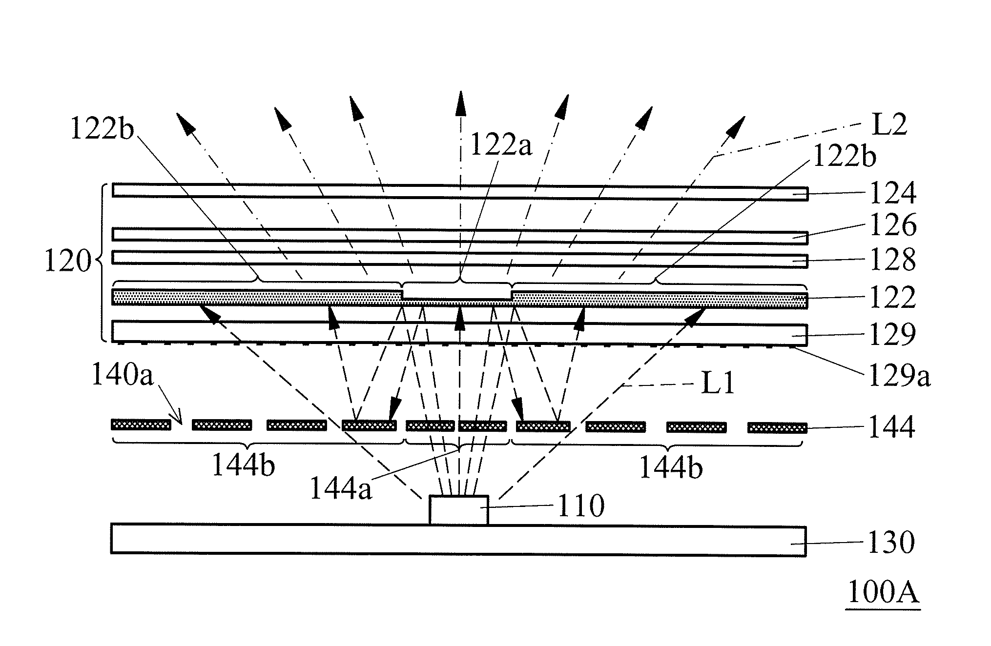
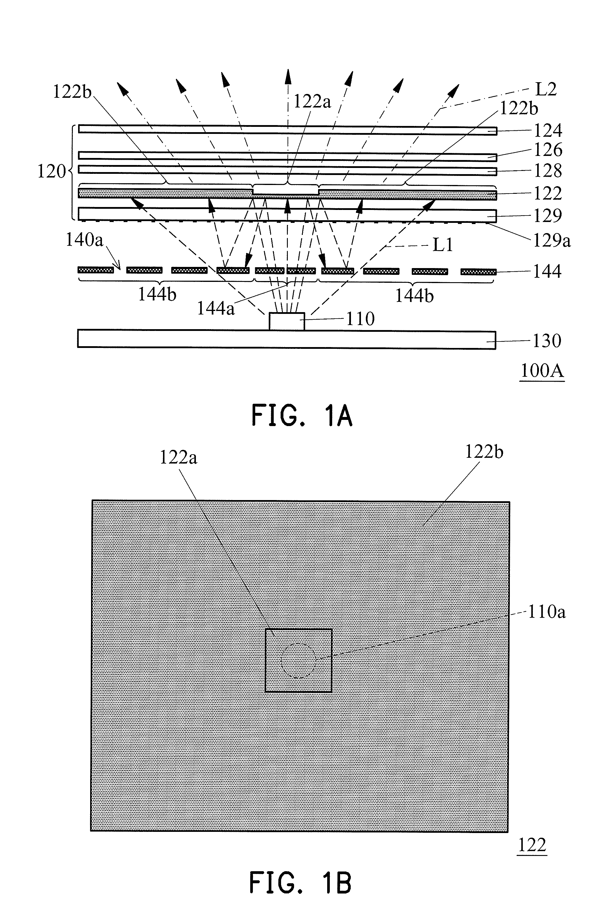
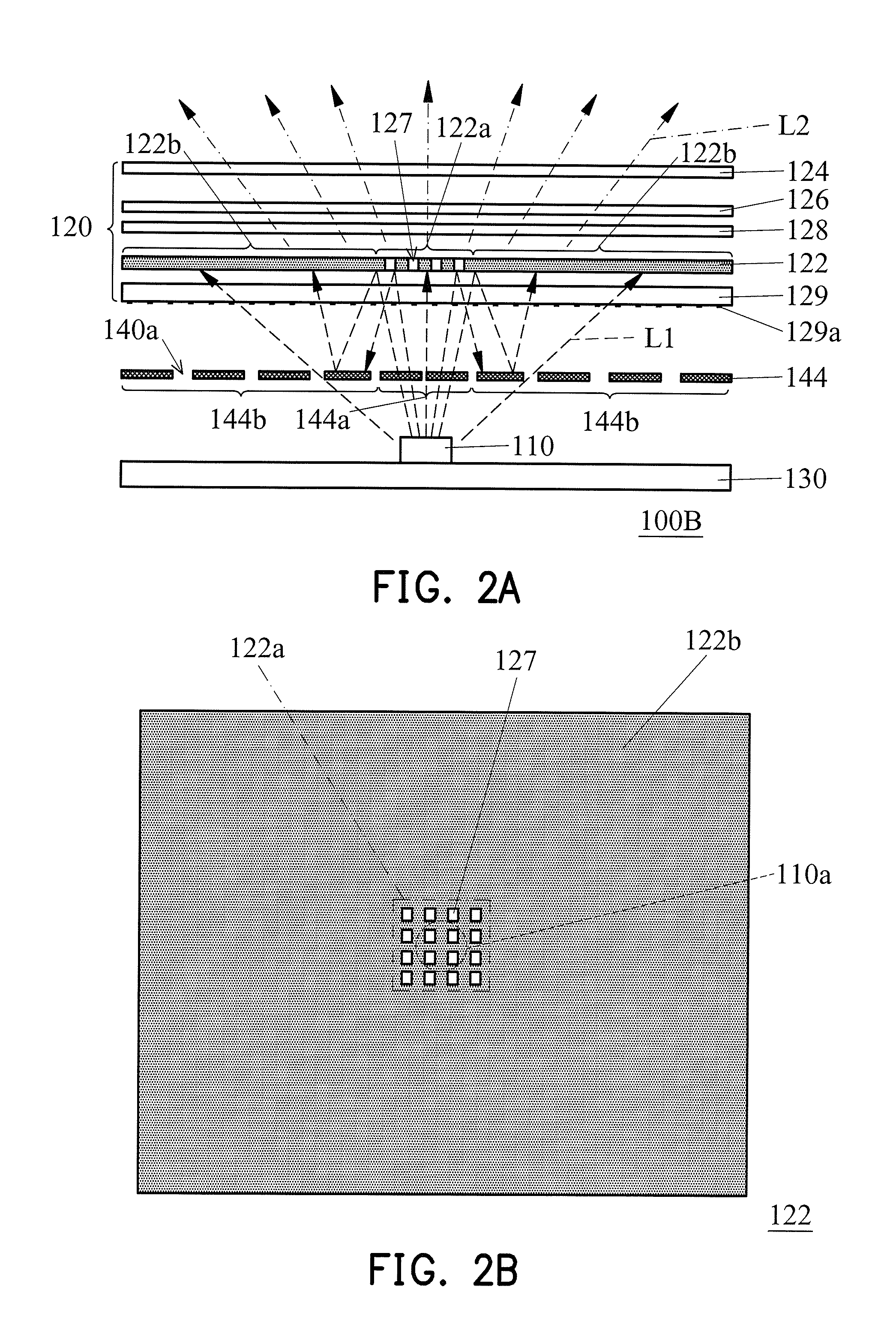
a backlight module and backlight technology, applied in the field of backlight modules, can solve the problems of non-uniform overall light-emitting color of the backlight module, and achieve the effect of eliminating color shift and uniform light-emitting color

Active Publication Date: 2016-12-15
AU OPTRONICS CORP
View PDF13 Cites 13 Cited by
  • Summary
  • Abstract
  • Description
  • Claims
  • Application Information

AI Technical Summary

Benefits of technology

The invention is a backlight module that can produce light in a way that eliminates color distortion and ensures consistent colors across the entire surface.

Problems solved by technology

As a result, in the region above the light source, more light is converted into the yellow light, which causes the overall light-emitting color of the backlight module to be non-uniform, and this phenomenon is called color shift.

Method used


Image

  • Backlight module
  • Backlight module
  • Backlight module

Examples


Embodiment Construction

[0023]The invention can adjust an optical wavelength conversion efficiency in a specific region of an optical wavelength conversion film through various possible means, so as to lower a probability for the light in the specific region from being converted into other colors. For instance, by reducing a thickness of the optical wavelength conversion film in the specific region, by forming a plurality of openings on the specific region of the optical wavelength conversion film, or by lowering a concentration of optical wavelength converters in the specific region of the optical wavelength conversion film, etc.; in other words, the aforementioned effect can, for example, be achieved by reducing an amount of the optical wavelength converters contained per unit area in the specific region of the optical wavelength conversion film. Herein, the said ‘unit area’ includes the optical wavelength conversion film itself and regions that are removed due to the formation of openings. Namely, the a...


PUM


Abstract

A backlight module includes a light source and an optical film group. The light source is suitable for emitting a first light. The optical film group includes an optical wavelength conversion film, which is adapted to receive the first light and to convert the first light into a second light with different wavelength. The optical wavelength conversion film includes a first portion and a second portion, wherein a quantity of the first light received per unit area of the first portion of the optical wavelength conversion film is greater than a quantity of the first light received per unit area of the second portion of the optical wavelength conversion film. Furthermore, an optical wavelength conversion efficiency of the first portion of the optical wavelength conversion film with respect to the first light is smaller than an optical wavelength conversion efficiency of the second portion of the optical wavelength conversion film with respect to the first light.

Description

CROSS-REFERENCE TO RELATED APPLICATION[0001]This application claims the priority benefit of Taiwan application serial no. 104118905, filed on Jun. 11, 2015. The entirety of the above-mentioned patent application is hereby incorporated by reference herein and made a part of this specification.BACKGROUND OF THE INVENTION[0002]1. Field of the Invention[0003]The invention generally relates to a backlight module.[0004]2. Description of Related Art[0005]In recent years, as electronic products become common, the display panel that provides the display function for the electronic products has come into focus among designers. There are various types of display panels that can be selected for use according to the designs of the electronic products. Some of them are not provided with a light-emitting function, and thus a backlight module needs to be disposed under the display panel to serve as a light source, so as to achieve the display function.[0006]Such a backlight module usually includes ...

Claims


Application Information

Patent Timeline
Patent Type & Authority Applications(United States)
IPC IPC(8): F21K99/00F21V9/40
CPCF21K9/56F21Y2105/006F21Y2101/02F21V9/40F21S8/00G02F1/133603G02F1/133605G02F1/133606G02F1/133609G02F1/133614G02F1/133607F21K9/60
Inventor CHANG, CHI-SHENGMA, CHI-TANGLIN, SU-YI
Owner AU OPTRONICS CORP
Learn More