Integrated Barrel Assembly for Firearm

a barrel assembly and integrated technology, applied in the field of integrated barrel assemblies for use with firearms, can solve the problems of affecting the safety of firearms,

Inactive Publication Date: 2016-12-15
WIESBLOTT JUSTIN +1
View PDF3 Cites 2 Cited by
  • Summary
  • Abstract
  • Description
  • Claims
  • Application Information

AI Technical Summary

Benefits of technology

The integrated barrel assembly is a firearm component that can be used in firearms that require a barrel extension. It is designed to work with upper receiver assemblies and is made from a single piece of steel. The assembly includes a bolt head cavity, chamber, and bore that all work together to create a barrel cavity that extends from the breech end of the barrel to its muzzle end. The bolt head cavity is designed to work with the bolt head of the receiver assembly and includes angled feed ramps for loading and expelling cartridges. The bolt-locking lugs on the bolt head cavity engage with bolt lugs on the receiver assembly to create a steel-to-steel interlock that helps resist the forces of combustion when the firearm is fired. The entire barrel can be coated with a protective coating after it is machined and a gas port can be drilled through the barrel wall. The integrated barrel assembly simplifies the manufacturing process and improves the performance of firearms.

Problems solved by technology

Removing the barrel from the barrel assembly and replacing it with a new or different barrel, however, is complicated.
If not done properly, a misfit barrel can lead to cracking, fractures, or other structural failures of the entire barrel assembly.
One of the issues primarily associated with changing a barrel is that of insuring that proper headspace or chamber clearance distance between the shoulder in the cartridge chamber of the barrel and the bolt block face when the latter is in firing position.
A failure to provide adequate head space can result in jamming of the firearm due to the cartridge not properly sliding into the chamber opening in a direct axially aligned longitudinal position with the barrel.
Conversely, providing too much headspace can result in lite primer strikes resulting in misfires and additional wear on parts due to the additional forces needed to chamber the cartridges.
Too much headspace can cause the cartridge to rupture on firing, without the proper chamber seating around the cartridge body and neck, perhaps damaging the firearm and possible injuring the shooter.
Unfortunately, the traditional manufacturing process of making a separate barrel extension and barrel itself leads to several problems.
Second, the threads may become stripped or cross-threaded when the two components are mated.
Third, the connection between the mated components may loosen with time and use, requiring retightening or possibly also adding an adhesive, which can further compromise the components structure, hardness, or strength.
Fourth, over-tightening of the components can lead to eventual cracks or fractures.
Fifth, the precise measurements for optimizing the firearms functioning, chambering, internal pressure management, and accuracy, are not easily achieved when threading the barrel and barrel extension together.
Sixth, because the gas port is created after the coating process, it becomes vulnerable to corrosion and build-up as the raw exposed metal of the port itself is subjected to hot, high pressure, cartridge discharge gas residues.
Seventh, because the components are coated or treated prior to being assembled together, the coating or treatment can alter the threads on the barrel and barrel extension and compromise their threaded engagement.

Method used


Image

  • Integrated Barrel Assembly for Firearm
  • Integrated Barrel Assembly for Firearm
  • Integrated Barrel Assembly for Firearm

Examples


Embodiment Construction

[0026]The embodiments disclosed herein are illustrated by way of example and not by way of limitation in the figures of the accompanying drawings in which like references indicate similar elements. It should be noted that references to “an” or “one” embodiment in this disclosure are not necessarily to the same embodiment, and they mean at least one. Additionally, where the shapes, relative positions and other aspects of the parts described in the embodiments are not clearly defined, the scope of the embodiments is not limited only to the parts shown, which are meant merely for the purpose of illustration. Also, while numerous details are set forth, it is understood that some embodiments may be practiced without these details. In other instances, well-known structures and techniques have not been shown in detail so as not to obscure the understanding of this description.

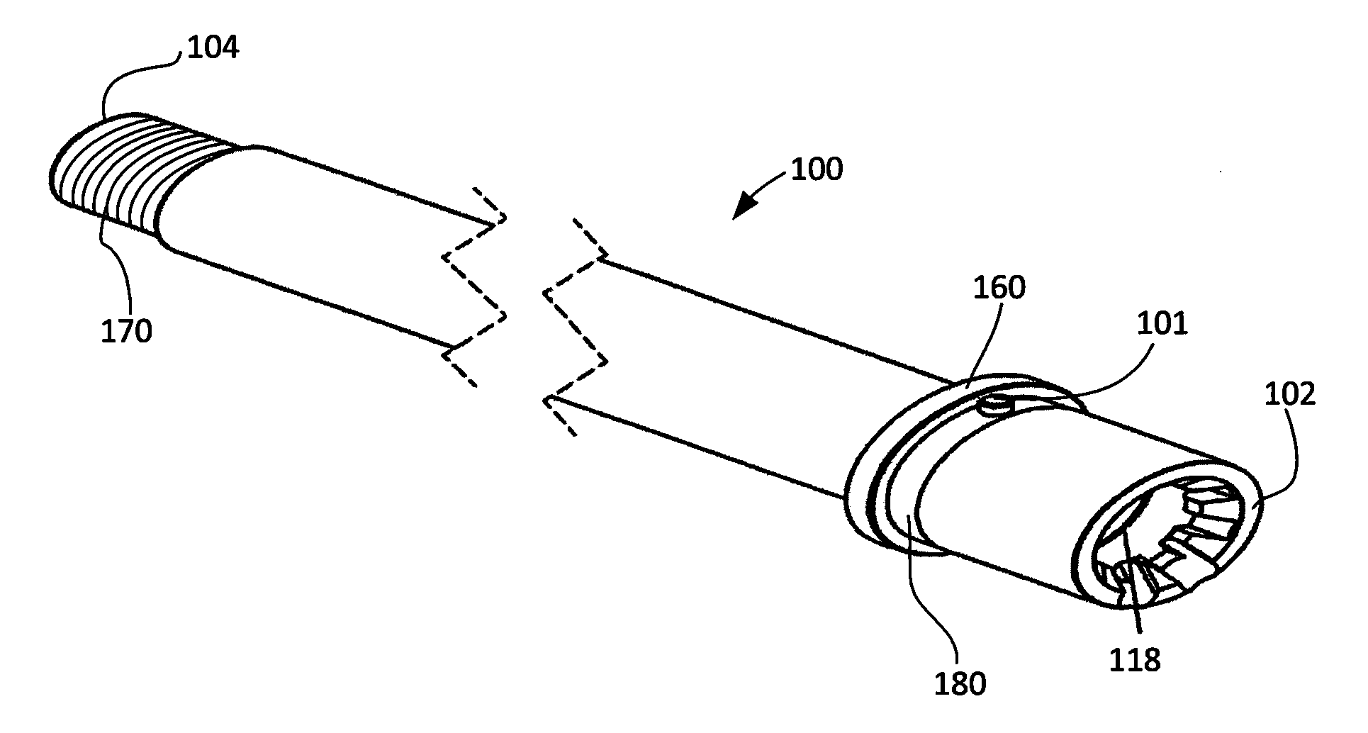
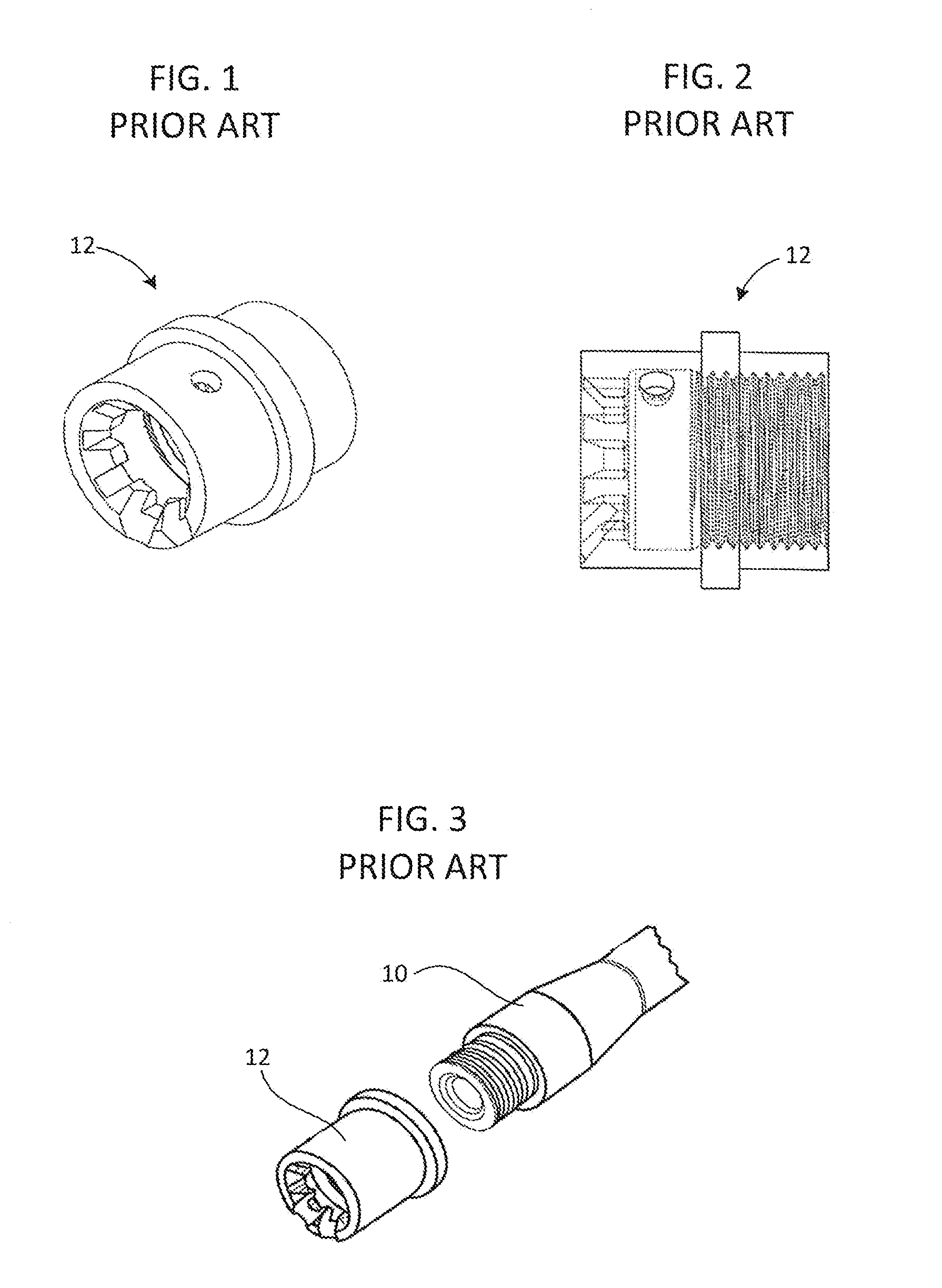
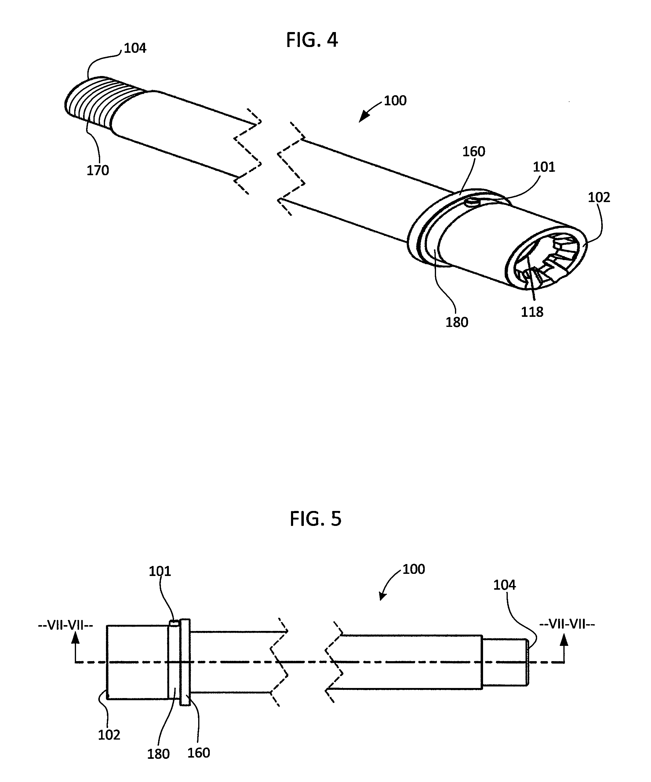
[0027]FIGS. 1-3 illustrate the prior art two-component barrel assembly, and FIGS. 4-10 illustrate the integrated ba...


PUM


Abstract

An integrated barrel assembly, configured to cooperate with a firearm receiver assembly firearm, comprises a barrel having a breech end and a muzzle end and a connector for securing and aligning it with the receiver assembly. The design eliminates the need for a separate barrel and barrel extension and improves the structural integrity and performance of the firearm. The barrel defines a bolt head cavity, a chamber, and a bore all in fluid communication and serially extending from its breech end to muzzle end, and an internal breech face is created where the bolt head cavity meets the chamber. The bolt head cavity comprises bolt-locking lugs and angled feed ramps, and the chamber and bore are configured to cooperate with a particular cartridge case and projectile. The barrel preferably comprises steel or a steel alloy and a coating applied to the barrel's outer surface, inner surface, ends, and gas port.

Description

FIELD OF THE INVENTION[0001]The present invention relates to firearms and, more particularly, to an integrated barrel assembly for use with a firearm.BACKGROUND OF THE INVENTION[0002]In general, firearms comprise at least a receiver assembly and a barrel assembly. The receiver assembly includes all of the moving parts that load, fire, and eject the firearms shells or cartridges. The barrel assembly attaches to and cooperates with the receiver assembly and includes the long metal tube with a bore that provides the exit path for the discharging projectile. Once the projectile is fired, due to expanding gas forces, it travels down the barrel from its initial position at the breech end of the barrel through an opening in the barrel's muzzle. In order for the firearm to operate properly and to achieve a high level of accuracy, the specifications of the barrel must correspond to the type and size of bullet being fired. For example, the bore of the barrel corresponds to the caliber of bull...

Claims


Application Information

Patent Timeline
Patent Type & Authority Applications(United States)
IPC IPC(8): F41A21/48F41A21/22F41A21/28
CPCF41A21/484F41A21/22F41A21/28
Inventor WIESBLOTT, JUSTINARRIA, ANTHONY
Owner WIESBLOTT JUSTIN
Why Eureka
Try Eureka