Projector

Inactive Publication Date: 2016-12-15
FUNAI ELECTRIC CO LTD
View PDF0 Cites 5 Cited by
  • Summary
  • Abstract
  • Description
  • Claims
  • Application Information

AI Technical Summary

Benefits of technology

This patent describes a new optical system for a projector that can shape the beam shape of a laser beam from an elliptic to circular shape while reducing the number of components in the overall optical system. The system includes two lens surfaces, one of which generates astigmatism in the laser beam and the other of which converts the beam into a parallel beam. The shaping of the beam shape is achieved without reducing the overall beam radius. By shaping the beam shape, the laser beam can be more efficiently utilized and the overall optical system can be made smaller.

Problems solved by technology

In a case where the laser beam having the elliptic shape beam shape is irradiated directly onto the projection surface, the display resolution of the image may deteriorate.
However, in the above mentioned conventional projector, a size of the shaping prism is relatively large.
Therefore, a problem arises where the entire optical system including the shaping prism becomes larger and consequently the entire projector becomes larger.

Method used


Image

  • Projector
  • Projector
  • Projector

Examples


embodiment 1

[0049]An optical element and a projector having the optical element according to a first embodiment is described below.

[1-1. Configuration of Head-Up Display Device]

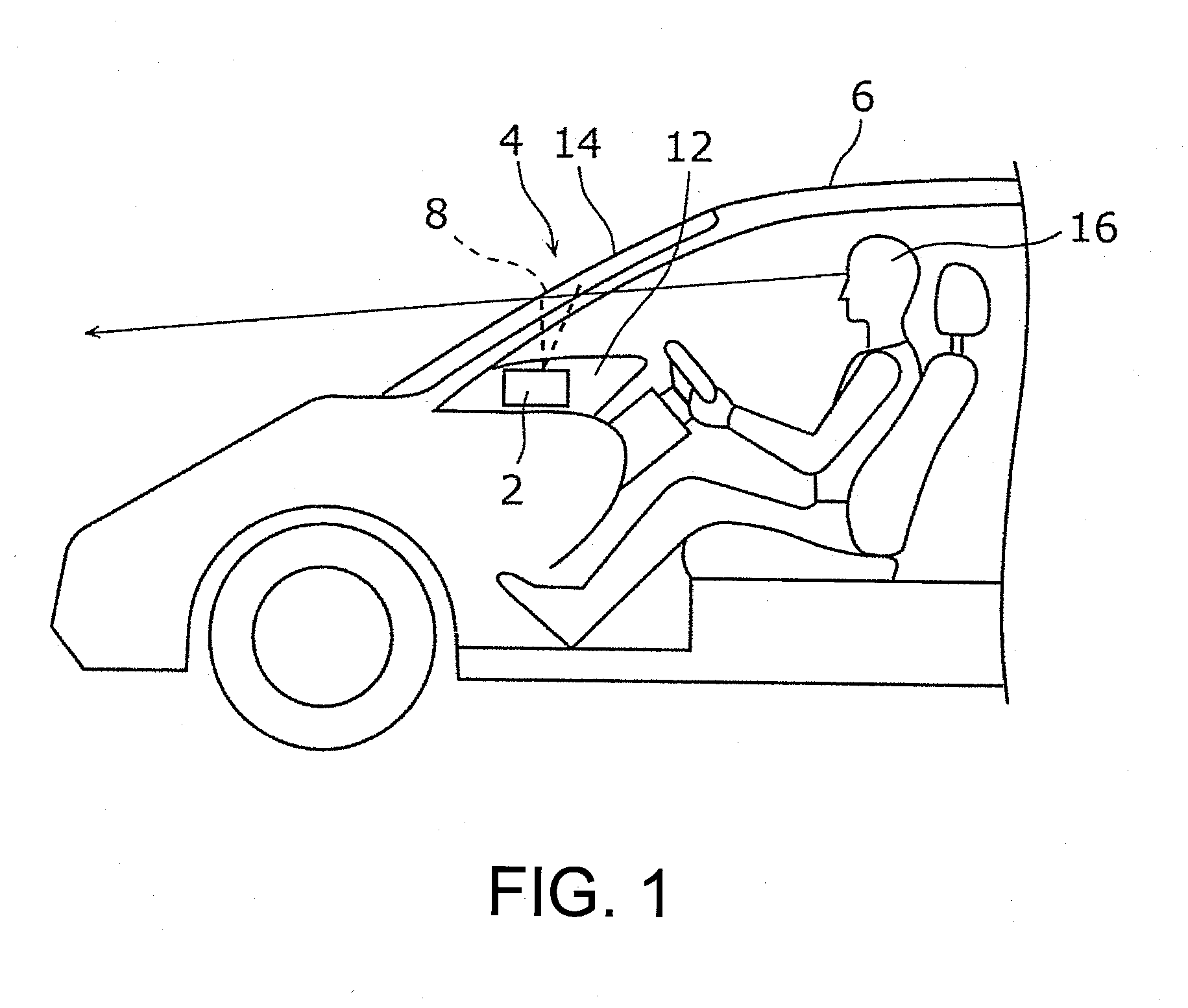
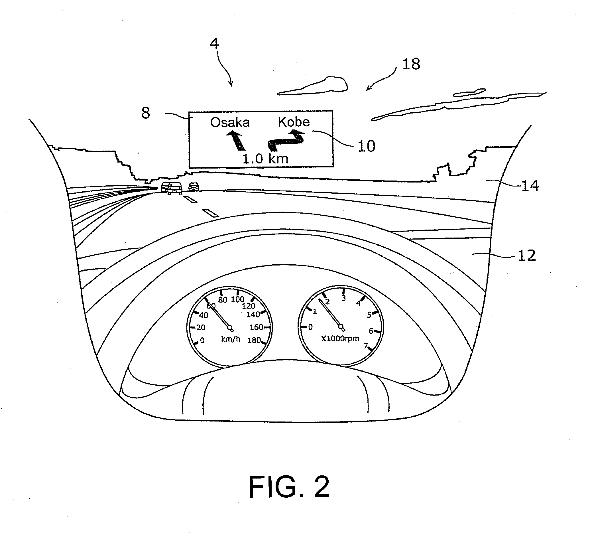
[0050]A projector 2 according to the first embodiment, for example, is mounted to a head-up display device 4. First, a configuration of the head-up display device 4 is described with reference to FIGS. 1 and 2. FIG. 1 is to describe a configuration of a head-up display device 4 equipped with the projector 2 according to a first embodiment. FIG. 2 illustrates a display sample of an image 10 by the head-up display device 4 of FIG. 1.

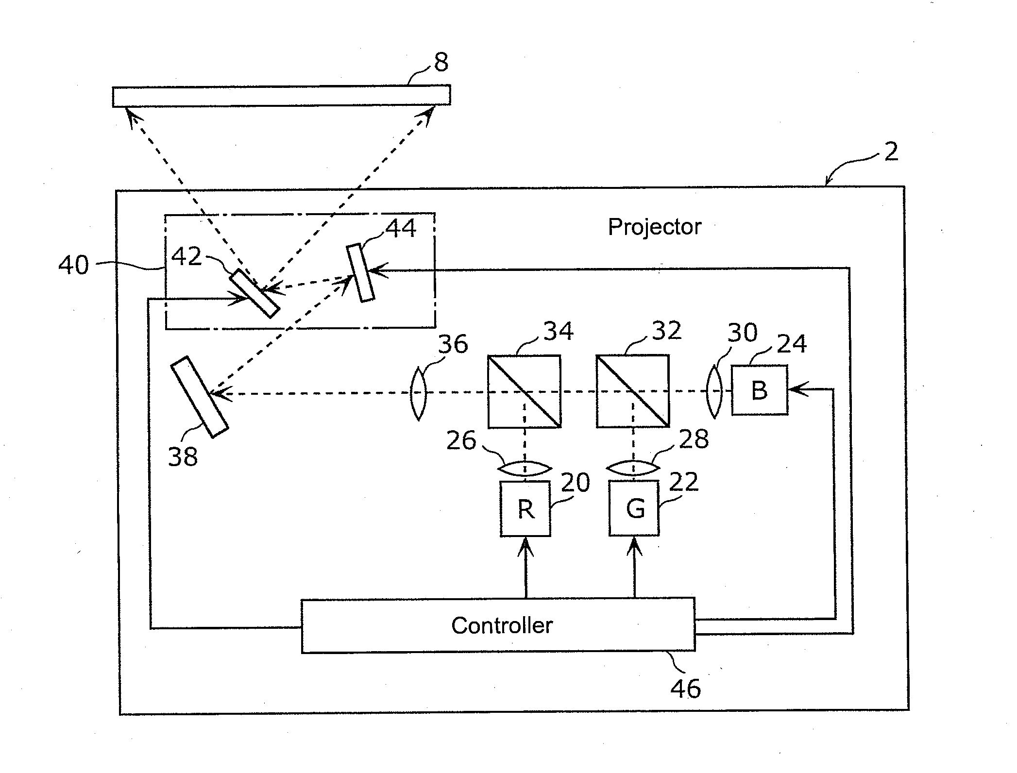
[0051]As shown in FIG. 1, the head-up display device 4, for example, is mounted to an automobile 6, and includes the projector 2 and a combiner 8 (also referred to as “projection surface 8” below). The projector 2 projects the image 10 onto the combiner 8, and is disposed in a dashboard 12 of the automobile 6. The combiner 8, for example, is constructed by a half mirror or such, and is disposed...

embodiment 2

[0081]Next, a configuration of the first optical element 26A according to a second embodiment is described with reference to FIG. 8. FIG. 8 is a side view illustrating a first optical element 26A according to a second embodiment. In the following embodiments, the same reference numbers as the aforementioned first embodiment are used to describe the same components, and their description thereof is omitted.

[0082]In the first optical element 26A according to the second embodiment, a shape of a second lens surface 54A that is formed on the emitting surface 50 is different compared to the aforementioned first embodiment. Namely, as is shown in FIG. 7, a shape of the second lens surface 54A is a spherical shape. A radius of curvature of the second lens surface 54A, for example, is −1.48 mm.

[0083]Even with this configuration, similar to the aforementioned first embodiment, the laser beam that is shaped by the first lens surface 52 is converted from a divergent beam into a parallel beam by...

embodiment 3

[0084]Next, a configuration of the first optical element 26B according to the third embodiment is described with reference to FIGS. 9 and 10. FIG. 9 is a perspective view illustrating a first optical element 26B according to a third embodiment. FIG. 10 is a side view illustrating a first optical element 26B according to a third embodiment.

[0085]In the first optical element 26B according to the third embodiment, a shape of a first lens surface 52B that has a convex shape formed on the incident surface 48B is different compared to the aforementioned first embodiment. That is to say, as shown in FIGS. 9 and 10, a shape of the first lens surface 52B has a first radius of curvature in a first direction (Y axis direction), and has a second radius of curvature in a second direction (X axis direction) that is orthogonal to the first direction, and is a so-called biconic surface shape. The first radius of curvature and the second radius of curvature are different in size. Preferably, a ratio...


PUM


Abstract

A projector is provided, having a light source emitting a laser beam; an optical element, which the laser beam emitted by the light source passes through; a projection component, projecting an image onto a projection surface by irradiating the laser beam emitted from the optical element onto the projection surface while scanning. The optical element has an incident surface, where the laser beam emitted by the light source is incident; and an emitting surface, where the laser beam incident to the incidence surface is emitted. A first lens surface, shaping a beam shape of the laser beam from elliptic into circular by astigmatism generated in the laser beam, is formed on one of the incident and the emitting surfaces, and a second lens surface, converting the laser beam from a divergent beam into a parallel beam, is formed on the other one of the incident the emitting surfaces.

Description

CROSS-REFERENCE TO RELATED APPLICATION[0001]This application claims the priority benefit of Japan application no. JP2015-120570, filed on Jun. 15, 2015. The entirety of the above-mentioned patent application is hereby incorporated by reference herein and made a part of this specification.BACKGROUND OF THE DISCLOSURE[0002]Field of the Disclosure[0003]The disclosure relates to a projector.[0004]Description of Related Art[0005]A projector that projects a color image on to a projection surface by synthesizing a laser beam of a red component (R), a laser beam of a green component (G) and a laser beam of a blue component (B), and irradiating the synthesized laser beam on to the projection surface while scanning is known in the art (for example, refer to patent document 1, Japanese Laid Open Patent Publication No. 2011-197217).[0006]A conventional projector includes a first laser diode for generating the laser beam of the red component, a second laser diode for generating the laser beam of...

Claims


Application Information

Patent Timeline
IPC IPC(8): H04N9/31G02B27/09G02B27/01G02B27/30
CPCH04N9/3152H04N9/3129H04N9/3161G02B2027/0112G02B27/0966H04N9/3164G02B27/0101G02B27/30G03B21/2033G03B21/208G02B3/06G02B27/0911G02B27/0955G02B27/104G02B19/0052
Inventor OKAMOTO, KENJI
Owner FUNAI ELECTRIC CO LTD
Why Eureka
Try Eureka