Guide Device for Retaining Ties in Masonry Walls
- Summary
- Abstract
- Description
- Claims
- Application Information
AI Technical Summary
Benefits of technology
Problems solved by technology
Method used
Image

Examples
Embodiment Construction
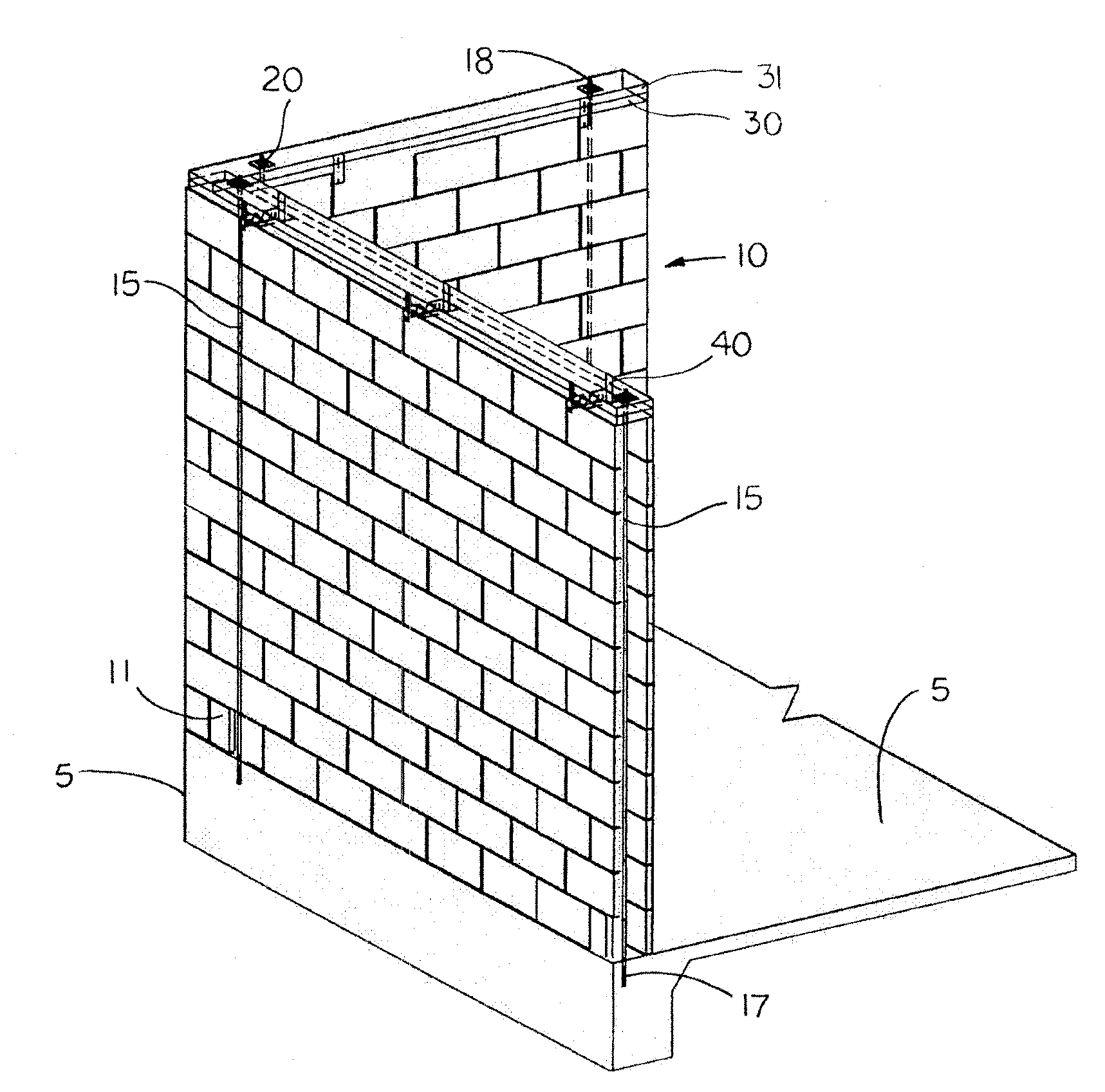
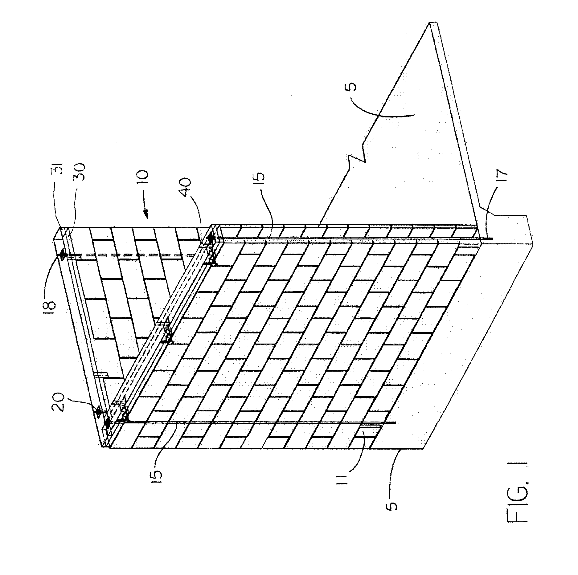
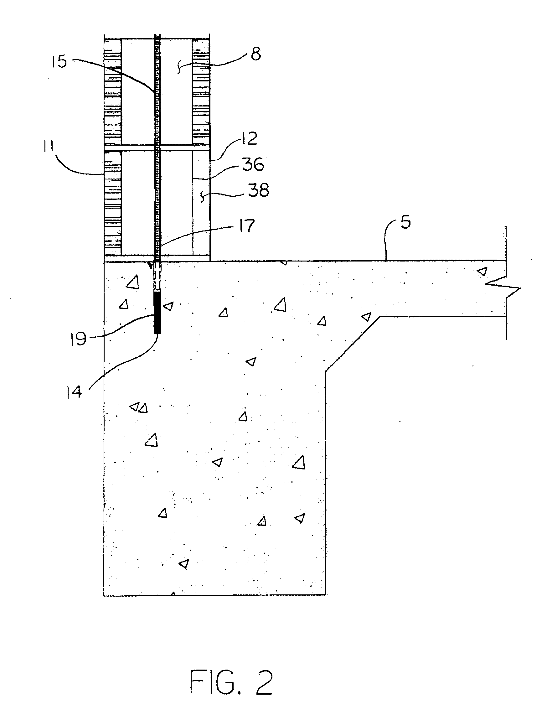
[0011]The present system and apparatus provides masonry structures adequate resistance to uplift, shear, and overturning forces caused by wind and / or seismic loading events. The force resistance is accomplished by installing tension tie members at spacing required by the wind and / or seismic loads present. A continuous tension load path is developed from the top of the exterior load bearing masonry wall to the foundation by using a tension member, such as a wire rope.
[0012]The retaining tie system is installed by locating access blocks that correspond to the anchor points identified by structural analysis and installing a knock-out in the side of each of the access blocks. The knock-out enables access to the top of the foundation, and an anchor hole is drilled into the top surface of the foundation. The anchor hole is then covered with a protective member to prevent intrusion of unwanted debris.
[0013]At the top of the CMU wall, an elongated base plate is seated across the top of the ...
PUM
 Abstract
Description
Claims
Application Information
PatSnap Eureka turns technology decisions into work you can execute. Powered by our Innovation Knowledge Graph, it runs expert workflows across engineering, life sciences, materials and intellectual property. Get your review-ready output in minutes.


