
Line blind valve

a blind valve and valve body technology, applied in the direction of valve arrangement, slide valve, pipe/joint/fitting, etc., can solve the problems of increasing the weight of the valve body b>10/b>, increasing the time required to insert or separate the double disk, and contaminating the fluid, so as to reduce the time required to open and block the pipeline, the effect of fundamentally preventing the dead spa

Active Publication Date: 2016-12-22
SAMMI MACHINERY
View PDF7 Cites 4 Cited by
  • Summary
  • Abstract
  • Description
  • Claims
  • Application Information

AI Technical Summary

Benefits of technology

The present invention aims to provide a line blind valve that can reduce weight of the blind, reduce time for opening and blocking pipeline, prevent dead space, and increase working efficiency and product reliability. The valve body is designed to be simple and compact, with a reduced number of components. Additionally, a third gasket may be provided to seal a gap between the stepped portion and the ring gear. The invention also simplifies the manufacturing process of the line blind valve.

Problems solved by technology

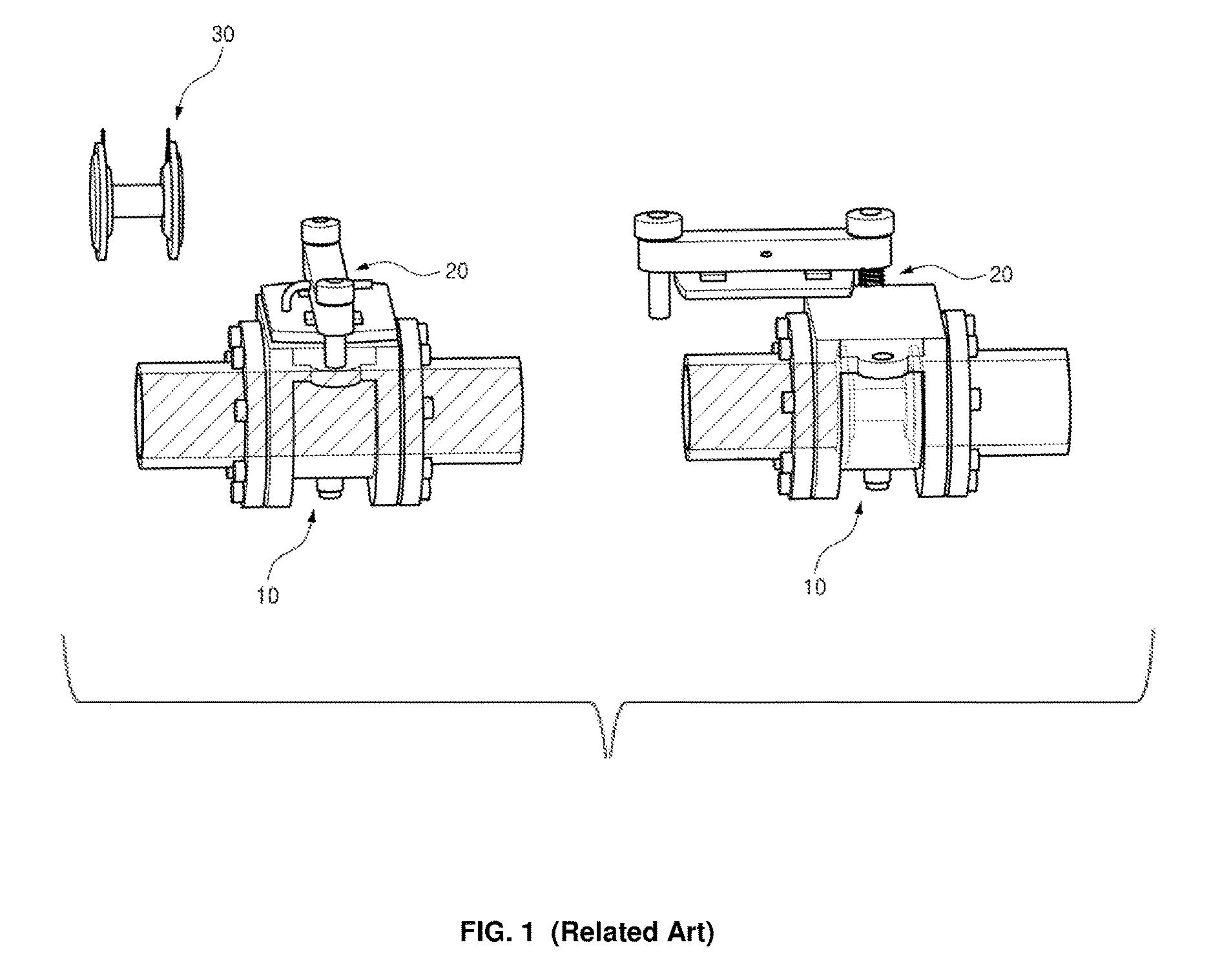
It is problematic in that the line blind valve according to the related art requires a dedicated device since it is hard to lift weight of the double disk 30 by human power, thereby increasing time required to insert or separate the double disk 30.
Furthermore, in the line blind valve according to the related art, since dead space is formed between the double disk 30 and the valve body 10, it is problematic in that different types of fluids are mixed or are gathered in the dead space, thereby contaminating the fluids.
Thus, it is problematic in that weight of the valve body 10 is increased.

Method used


Image

  • Line blind valve
  • Line blind valve
  • Line blind valve

Examples


Embodiment Construction

[0024]Hereinbelow, exemplary embodiments of the present invention will be described in detail with reference to the accompanying drawings.

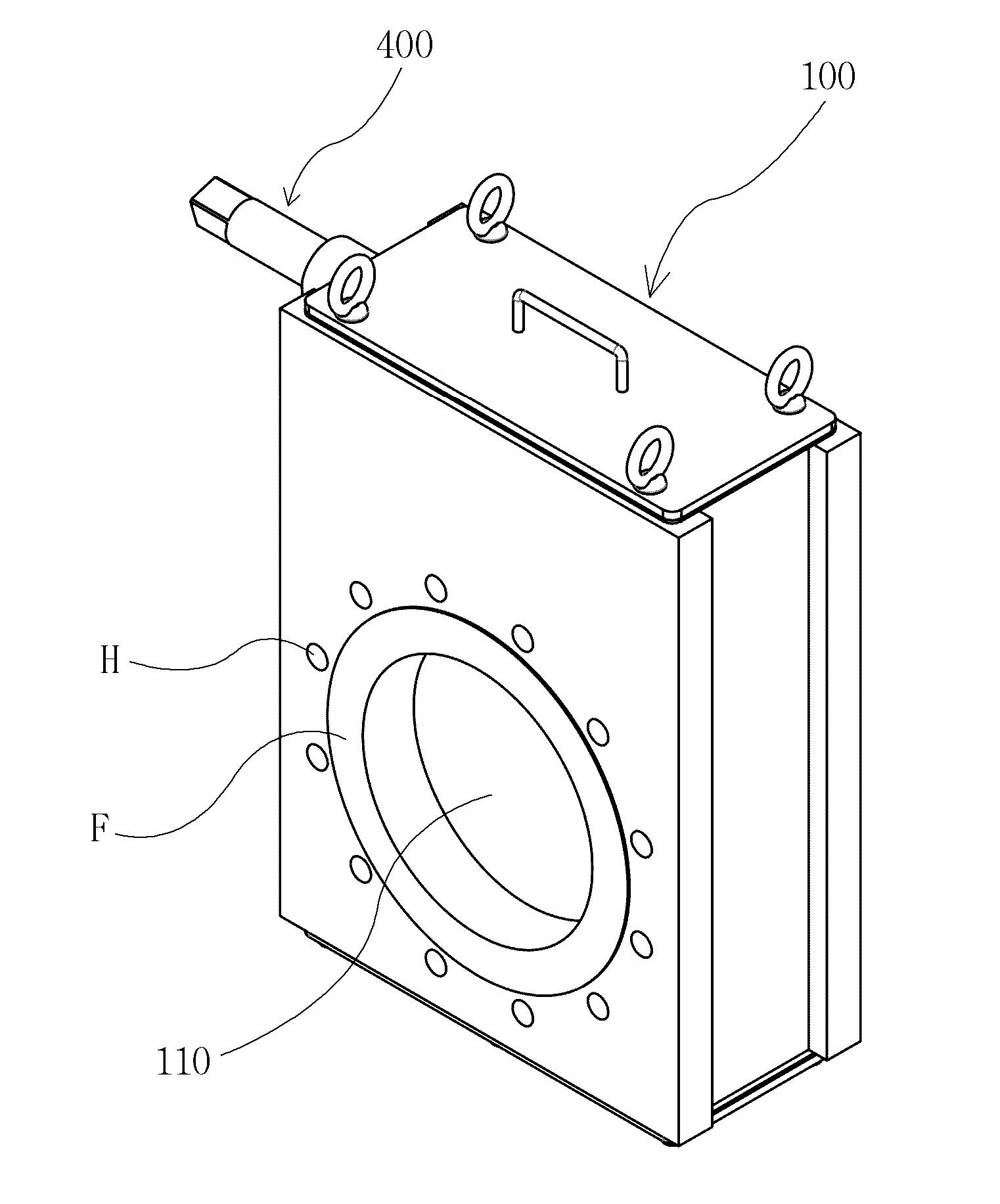
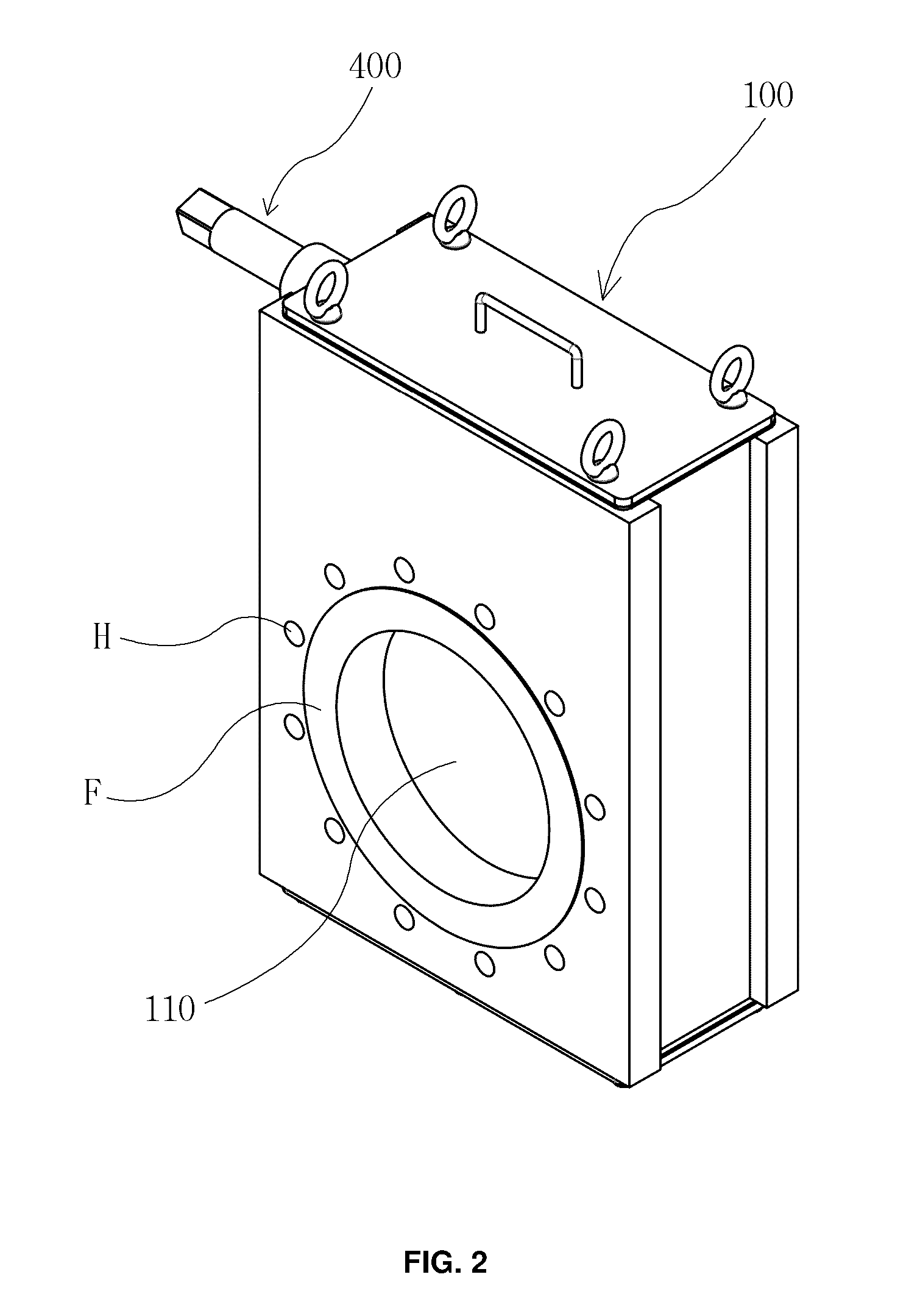
[0025]As shown in FIGS. 2 and 3, which are perspective and side views illustrating a line blind valve according to the present invention, and as shown in FIG. 4, which illustrates a sectional view taken along line A-A of FIG. 3, the present invention relates to the line blind valve installed between pipes so as to open or block a pipeline for maintenance of the pipeline or for urgently blocking the pipeline in case of emergency. The line blind valve includes a valve body 100, an opening blind 200, a blocking blind 300, and a gear unit 400.

[0026]The valve body 100 is installed between pipes, and the opening blind 200 or the blocking blind 300 is inserted into the valve body 100 so as to open or block the pipeline. The valve body 100 is formed in a container shape of which upper and lower portions are open so that upper and lower covers may be attac...


PUM


Abstract

A line blind valve installed between pipes to open or block a pipeline, in which the line blind valve includes: a valve body having opening portions formed at front and rear sides thereof, respectively; a front sheet formed from the opening portion of the front side toward an inside of the valve body, and a rear sheet formed from the opening portion of the rear side toward the inside of the valve body; an opening blind installed during opening of the pipeline and a blocking blind installed during blocking of the pipeline, the opening and blocking blinds being inserted between the front and rear sheets; and a gear unit coupled to the rear sheet in a threaded manner, and configured to press the opening blind or the blocking blind toward the front sheet by moving forward so that the opening or the blocking blind is fixed to the front sheet, and is sealed.

Description

REFERENCE TO RELATED APPLICATIONS[0001]This is a continuation of pending International Patent Application PCT / KR2015 / 003789 filed on Apr. 15, 2015, which designates the United States and claims priority of Korean Patent Application No. 10-2014-0084906 filed on Jul. 8, 2014, the entire contents of which are incorporated herein by reference.FIELD OF THE INVENTION[0002]The present invention relates generally to a line blind valve. More particularly, the present invention relates to a line blind valve for controlling fluid flow by being connected to a pipe of a vessel or plant.BACKGROUND OF THE INVENTION[0003]In general, a line blind valve is located on a boundary of a pipe for a hydraulic test, and is configured to block and open fluid flow of a pipe. Furthermore, the line blind valve is installed in pipes for different types of fluids so as to prevent the fluids from being introduced into each other or to prevent the fluids from being mixed with each other. Usually, the line blind val...

Claims


Application Information

Patent Timeline
IPC IPC(8): F16K3/312F16K3/18F16K3/02
CPCF16K3/312F16K3/0227F16K3/18F16K3/0218F16L55/105
Inventor KIM, BYEONG-RYONG
Owner SAMMI MACHINERY
Learn More