Failure detection sensor, failure detection system, and structure

a failure detection system and sensor technology, applied in the direction of screws, load-modified fasteners, fastening means, etc., can solve the problems of torsional fracture and bend fracture, and achieve the effect of simple structure, easy detection of fracture signals, and short tim

Active Publication Date: 2016-12-22
HIEI KENSETSU
View PDF9 Cites 12 Cited by
  • Summary
  • Abstract
  • Description
  • Claims
  • Application Information

AI Technical Summary

Benefits of technology

[0029]According to the invention, when the failure detection sensor is attached to structural members of a structure, if the first member produces elastic deformation or plastic deformation due to any force applied to the structure, fracture and / or displacement of the second member occurs. Therefore, by detecting the fracture and / or displacement of the second member, it is possible to detect that the first member fractures or excess displacement of the first member occurs. As a result, it is possible to detect the risk of the fracture before the structural members, and thus the structure fractures. Furthermore, for example, if the failure detection sensor is constructed so that when the second member fractures, a fractured piece of the second member springs out from the first member, it is possible to detect easily a fracture signal by detecting spring out of the fractured piece. Therefore, using the fracture signal, it is possible to detect and notify the risk of the fracture completely automatically in a short time around the clock. In addition, since the failure detection sensor can be constructed by the first member and the second member, its structure is simple and it can be realized in a low price. According to the failure detection system using the failure detection sensor, it is possible to notify and / or display outside the risk of the failure before the failure of the structure occurs. Therefore, it is possible to take measures to prevent the failure of the structure. Or, it is possible for persons to evacuate from the structure. As a result, it is possible to prevent human and physical damages from occurring. Furthermore, by selecting an attaching method of the failure detection sensor to the structure, it is possible to detect any one of tensile fracture, shear fracture, compression fracture, bend fracture, torsion fracture, etc.

Problems solved by technology

However, the watching method described in patent literature 1 only detects that fracture of the bolt occurs or the object attached to the structure falls off and cannot detect before fracture of the bolt occurs or the object attached to the structure falls off.
Furthermore, the axial force control bolt described in patent literature 2 can control only the axial force of the bolt, and therefore can detect only tensile fracture and cannot detect shear fracture, bend fracture, torsional fracture, etc.

Method used


Image

  • Failure detection sensor, failure detection system, and structure
  • Failure detection sensor, failure detection system, and structure
  • Failure detection sensor, failure detection system, and structure

Examples


first embodiment

1. The First Embodiment

Failure Detection Sensor

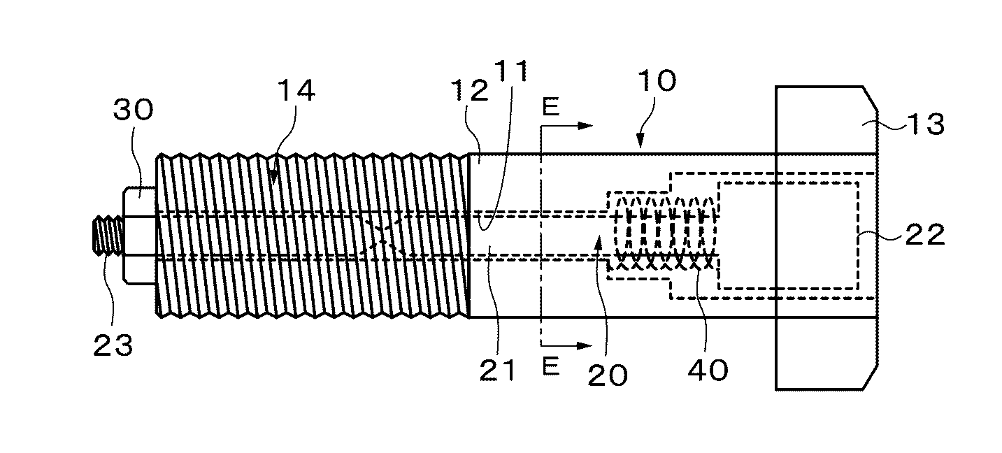
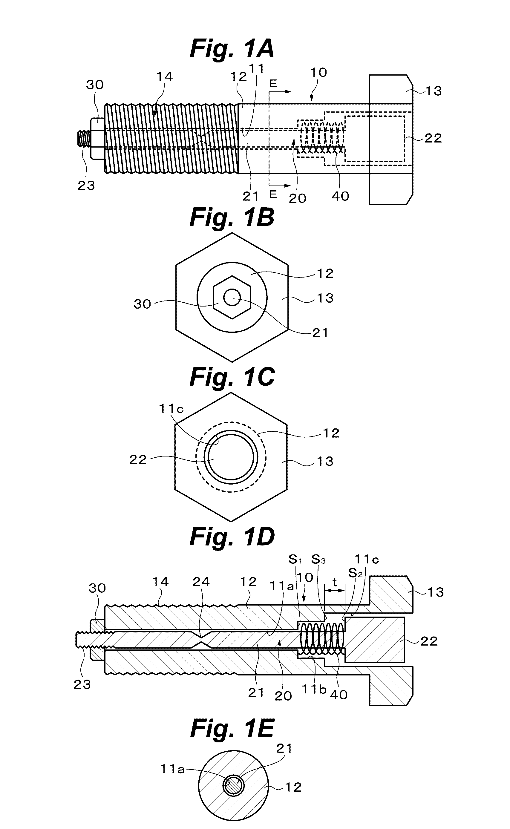
[0130]FIG. 1A, FIG. 1B, FIG. 1C, FIG. 1D and FIG. 1E show the failure detection sensor according to the first embodiment, where FIG. 1A is a front view, FIG. 1B is a left side view, FIG. 1C is a right side view, FIG. 1D is a longitudinal cross sectional view and FIG. 1E is a cross sectional view along the E-E line of FIG. 1A. The failure detection sensor is especially suitable for detection of tensile fracture.

[0131]As shown in FIG. 1A, FIG. 1B, FIG. 1C, FIG. 1D and FIG. 1E, the failure detection sensor comprises a hexagonal bolt-like first member 10 with a hollow part 11 and a circular rod-like second member 20 which is inserted into the hollow part 11 of the first member 10. The second member 20 has fracturing characteristics such that it fractures during elastic deformation or plastic deformation of the first member 10.

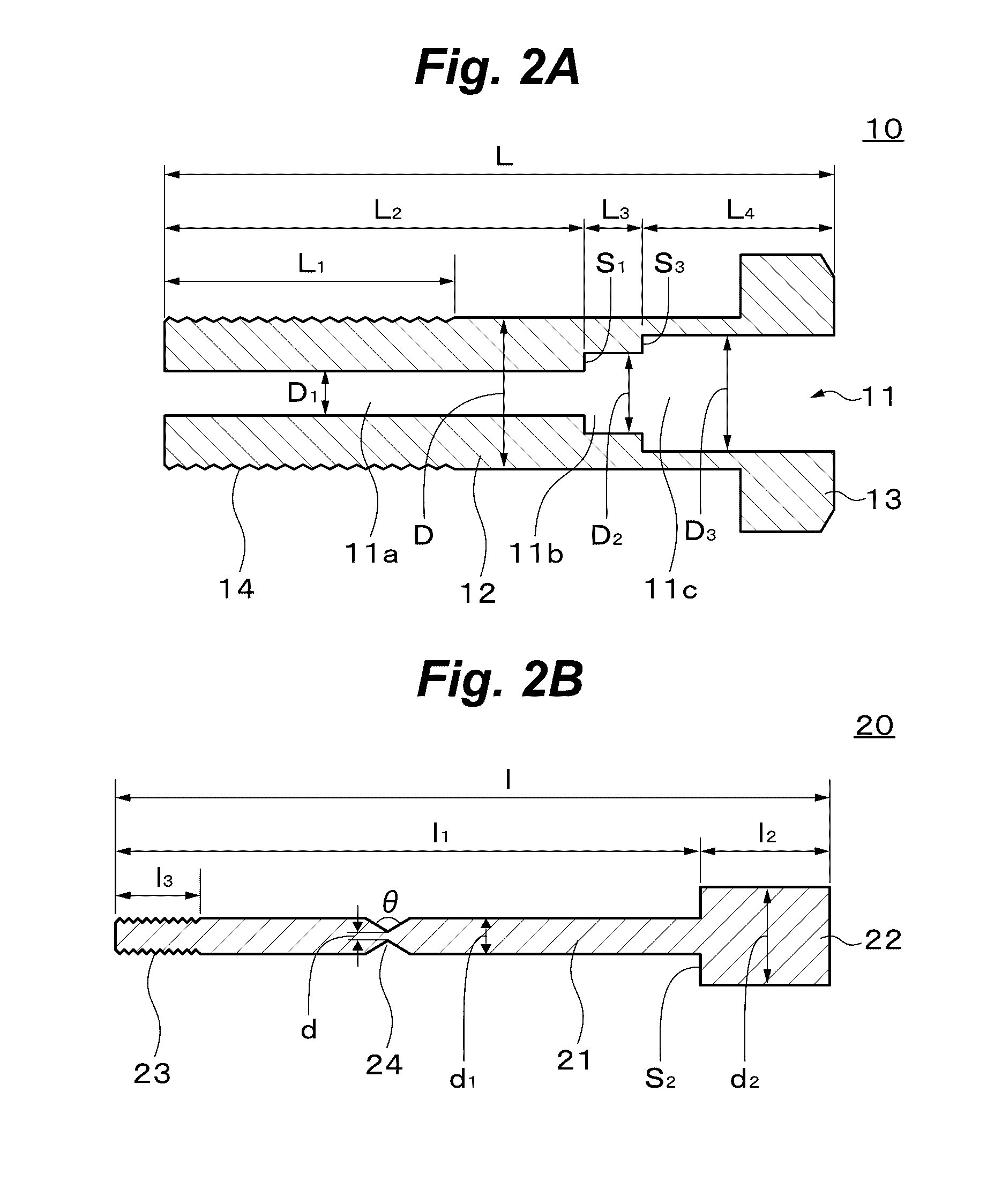
[0132]FIG. 2A shows details of the first member 10, and FIG. 2B shows details of the second member 20. The total len...

second embodiment

2. The Second Embodiment

Failure Detection Sensor

[0145]FIG. 8A, FIG. 8B, FIG. 8C, FIG. 8D and FIG. 8E show the failure detection sensor according to the second embodiment, where FIG. 8A is a front view, FIG. 8B is a left side view, FIG. 8C is a right side view, FIG. 8D is a longitudinal cross sectional view and FIG. 8E is a cross sectional view along the E-E line of FIG. 8A. FIG. 9A shows details of the first member 10, and FIG. 9B shows details of the second member 20.

[0146]As shown in FIG. 8A, FIG. 8B, FIG. 8C, FIG. 8D, FIG. 8E, FIG. 9A and FIG. 9B, in the failure detection sensor, a female screw 15 is cut on the inner peripheral surface of the hollow part 11 of the axial part 12 of the first member 10 over a length L5 from the front end of the axial part 12. The male screw 23 is cut on the outer peripheral surface of the axial part 21 of the second member 20 over the length l3 from the front end of the axial part 21 larger than that of the first embodiment. And the male screw 23 o...

third embodiment

3. The Third Embodiment

Failure Detection Sensor

[0149]In the failure detection sensor according to the third embodiment, the nut 30 fitted to the male screw 23 of the axial part 21 of the second member 20 is fixed to the front part of the first member 10 by welding, gluing, brazing, etc. With this, the front part of the second member 20 is fixed to the front part of the first member 10.

[0150]Other than the above of the failure detection sensor is the same as the failure detection sensor according to the first embodiment.

[0151]According to the third embodiment, the same advantages as the first embodiment can be obtained.


PUM

PropertyMeasurementUnit
thicknessaaaaaaaaaa
diameteraaaaaaaaaa
lengthaaaaaaaaaa

Abstract

Provided is a failure detection sensor which, when attached to structural members of various structures such as buildings can easily detect the risk of the failure of the structural members, and thus the structure, before such failure occurs and has a simple structure, which leads to realization at a low price.
The failure detection sensor comprises: the first member 10 and the second member 20 provided in parallel with the first member 10 such that one end of the second member 20 is fixed to or restricted by the first member 10 and the other end of the second member 20 is not fixed to or restricted by the first member 10, having fracturing characteristics such that the second member 20 fractures during elastic deformation or plastic deformation of the first member 10. The failure detection sensor may have a compression coil spring 40 which applies a tensile force to the other end of the second member 20 on the opposite side of the one end. The first member 10 and the second member 20 are constituted of, for example, a round rod or a square rod and the first member 10 is constituted of, for example, a hollow rod. The second member 20 has a notch 24 which is a stress concentration site between the one end and the other end. The second member 20 is made of brittle materials.

Description

TECHNICAL FIELD[0001]This invention relates to a failure detection sensor, a failure detection system, and a structure, which are suitably applied, for example, to detect the risk of the failure of joints of various structures such as buildings.BACKGROUND ART[0002]For the purpose of joint (wide sense joint including connection and fastening) of structural members of various structures such as buildings, bridges, and tunnels, various joint technologies such as welding, rivets, bolts and nuts have been used. Since the failure of the joints of the structural members has a close relation to damage of the structure from the view of safety of the structure, it is necessary to examine damage of joints and a periodic examination must be made. Conventional general examination methods for this purpose are mainly a hammering test and visual inspection. However, especially the hammering test requires intuition and skill of inspectors, and therefore the inspectors are limited. Furthermore, gener...

Claims


Application Information

Patent Timeline
Patent Type & Authority Applications(United States)
IPC IPC(8): G01N3/08F16B5/06F16B31/02
CPCG01N3/08F16B5/0642F16B31/025F16B31/02H01H35/006F16B31/021
Inventor KONDO, TSUKASA
Owner HIEI KENSETSU
Why Eureka
Try Eureka