X-ray generator

a generator and x-ray technology, applied in the field of x-ray generators, can solve the problems of limiting the emitter density, extending the method to large arrays, and limiting the effect of the emitter current control,

Active Publication Date: 2016-12-22
ADAPTIX
View PDF2 Cites 12 Cited by
  • Summary
  • Abstract
  • Description
  • Claims
  • Application Information

AI Technical Summary

Benefits of technology

The present invention provides a way to control the activation of multiple x-ray sources individually without the need for high voltage switching. It also allows for the synchronization of the activation sequence with the emitter electrons and detecting elements in the x-ray imaging application. The invention includes an x-ray generator with multiple electron field emitters and solenoid coils, which create a magnetic field to defocus and / or deflect the electrons emitted from the emitter. The high atomic number material in the target material helps to direct the electrons towards the low atomic number material, resulting in higher image quality. Overall, the invention provides a means to control the x-ray emission and improve the accuracy and quality of x-ray imaging.

Problems solved by technology

A well known problem in electron and x-ray generation is the control of the electron current and hence of the resulting x-ray flux.
Extending these methods to large arrays can prove impractical and costly.
Grids can limit the emitter density and introduce a source of arcing and breakdown.
Transistor arrays can lead to complex switching controls and the low voltages of emission can lead to reduced current due to space charge effects.

Method used


Image

  • X-ray generator
  • X-ray generator
  • X-ray generator

Examples


Embodiment Construction

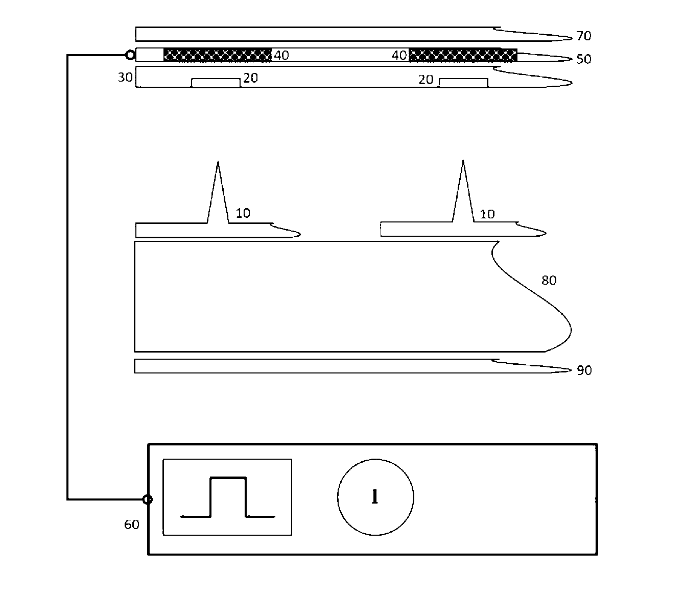
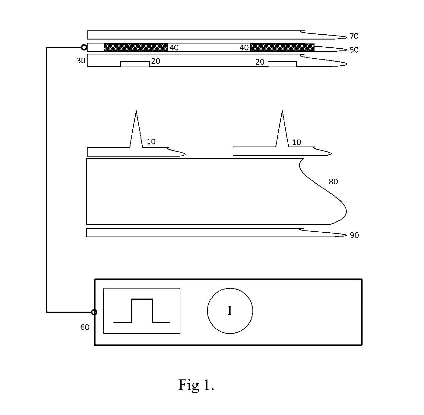
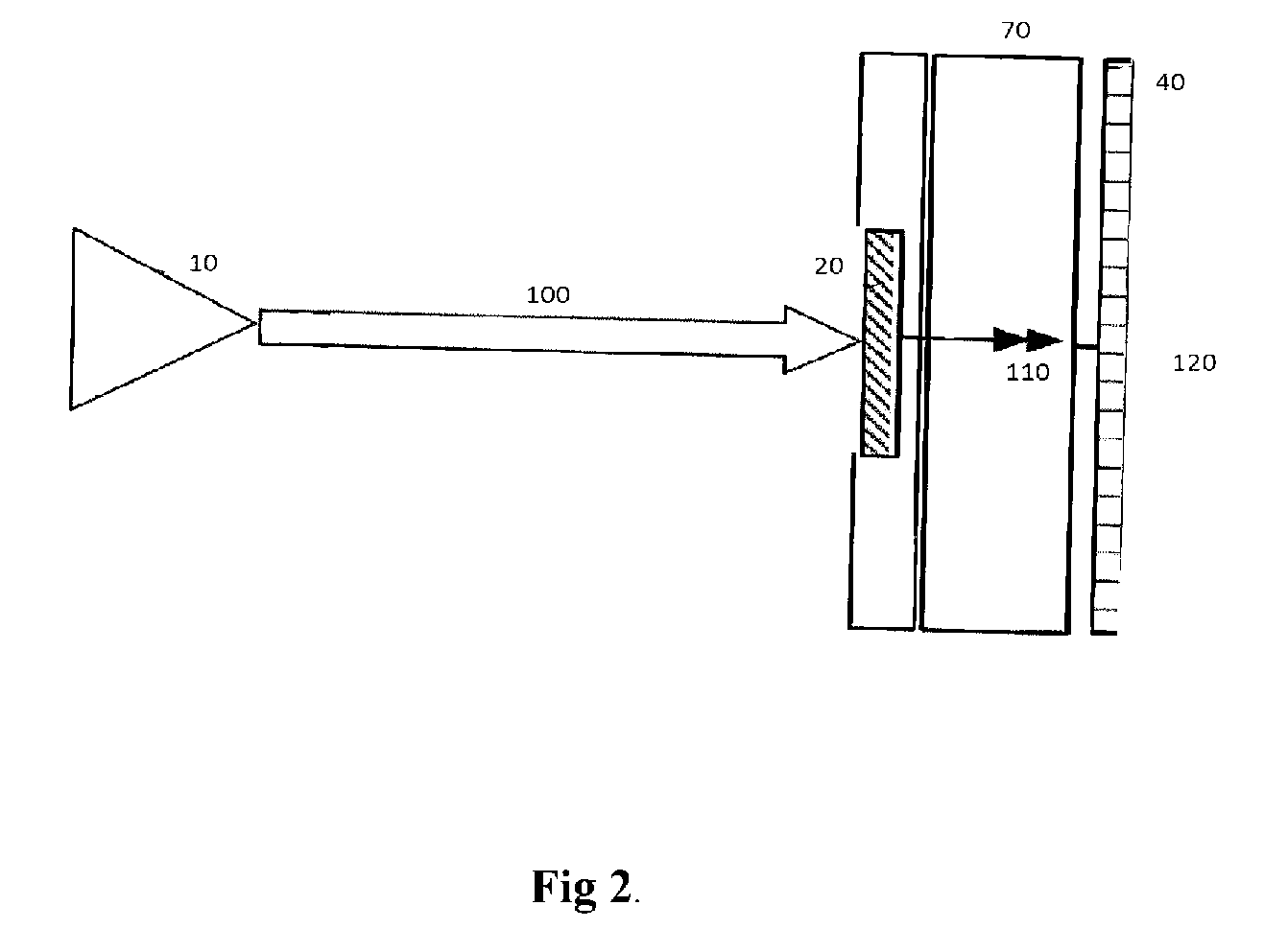
[0018]Embodiments of the present invention(s) will be described with respect to certain drawings but the invention(s) are not limited thereto but only by the claims. The drawings described are only schematic and are non-limiting. Each drawing may not include all of the features of the invention and therefore should not necessarily be considered to be an embodiment of the invention. In the drawings, the size of some of the elements may be exaggerated and not drawn to scale for illustrative purposes. The dimensions and the relative dimensions do not correspond to actual reductions to practice of the invention.

[0019]Furthermore, the terms first, second, third and the like in the description and in the claims, are used for distinguishing between similar elements and not necessarily for describing a sequence, either temporally, spatially, in ranking or in any other manner. It is to be understood that the terms so used are interchangeable under appropriate circumstances and that operation...


PUM


Abstract

An x-ray generator may include a plurality of electron field emitters; a target material; a plurality of energisable solenoid coils; and an electronic power and timing circuit. The generator may provide electrical current to at least one individual solenoid coil to create a magnetic field to cause the path of electrons emitted from the emitter closest to the energised solenoid coil to be defocused and / or deflected before the electrons reach the target material. The target material may comprise a low atomic number material and a high atomic number material, the high atomic number material being arranged in a regular pattern, such that, in use, the electrons may be aimed at either the high or the low atomic number material.

Description

CROSS-REFERENCE TO RELATED APPLICATIONS[0001]This application claims the benefit of International Application No. PCT / GB2015 / 050639 filed on Mar. 5, 2015, and published as WO 2015 / 132595 A1, and International Patent Application No. GB 1403901.0 filed on Mar. 5, 2014, which are hereby incorporated by reference in their entirety.FIELD OF INVENTION[0002]The present invention(s) relate generally to an x-ray generator and a method of obtaining an x-ray image of an object and finds particular, although not exclusive, utility in an x-ray generator comprising a plurality of x-ray sources.BACKGROUND[0003]In recent years there have been advances in the development of micrometer scale x-ray sources, such that it is now possible to produce a plurality of x-ray sources with a typical distance between the x-ray sources of the order of 100 μm to 1 cm or more.[0004]An example of such a two-dimensional x-ray source is provided in WO 2011 / 017645 “apparatus for producing x-rays for use in imaging”.[00...

Claims


Application Information

Patent Timeline
Patent Type & Authority Applications(United States)
IPC IPC(8): H01J35/30H01J35/06
CPCH01J35/30H01J2235/068H01J2235/087H01J35/065A61B6/4007H01J35/116H01J35/14
Inventor EVANSSTEVENS, ROBERTTRAVISH, GIL
Owner ADAPTIX
Why Eureka
Try Eureka