Desk chair mat

a technology for chairs and mats, applied in the field of chairs, can solve the problems of hand injury, problem of safe handling, awkward handling of chairs, etc., and achieve the effects of reducing the damage to the underlying carpet, facilitating the handling and display of chairs, and enhancing ease of handling

Inactive Publication Date: 2006-04-18
ROBBINS III EDWARD S
View PDF20 Cites 28 Cited by
  • Summary
  • Abstract
  • Description
  • Claims
  • Application Information

AI Technical Summary

Benefits of technology

[0008]A desk chair mat of the present invention is intended for interposition between a carpet upper surface and a chair, and can have a substantially planar upper surface suitable for interaction with a chair support structure that typically includes a plurality of wheels on the lower outside points of a spider. The desk chair mat has a perimeter defining an outer edge of the mat, and a lower surface parallel to the upper surface. The lower surface can include an array of blunt projections extending downwardly from the lower surface for engagement with the carpet. Each of the projections can have a smooth end surface spaced below the lower surface of the desk chair mat by a distance sufficient to penetrate into the carpet upper surface, typically by about 3 mm or more. The array of projections can be confined to a first selected area of the lower surface, while a second selected area of the lower surface can include a graphic that is visible through the upper surface of the chair mat. The array of projections in the first area resists lateral forces acting on the desk chair mat and thereby stabilizes the mat with respect to the carpet sufficiently to prevent any significant wear of the graphic in the second area.
[0009]The array of blunt projections can assume any number of appearances. The blunt projections can be linear, angular or curved. Usually, the vertical cross-sectional aspect ratio of the blunt projections is greater that one in a first direction and less than one in a direction normal to the first direction. The smooth end surfaces of the blunt projections can be generally parallel to the lower surface of the desk chair mat or arcuate. The smooth end surface of each of the blunt projections has an area sufficient to prevent penetration of the skin of someone handling the mat, which is believed to be at least about 8 mm2. The end surface of each of the blunt projections is sufficiently smooth to prevent abrasion of the skin of someone handling the mat.
[0010]The blunt projections can be aligned in spaced linear arrays. The resistance to lateral forces can be enhanced by arranging the blunt projections in a regular pattern wherein each projection is situated at an angle with respect to each nearest neighbor. The resistance to lateral forces can also be achieved by arranging the blunt projections in rows with the projections in adjacent rows being situated at an angle to each other. The blunt projections can cover a majority of the lower surface of the desk chair mat, but need not extend to any given area including the perimeter. The distance between the blunt projections can vary considerably, but is typically between about 1 and 4 cm. The first area containing the array of projections can be larger than the second area containing the graphic. The second area can be centrally located with the first area completely surrounding the second area. Alternatively, the second area can be confined to include a portion of the periphery.
[0011]A desk chair mat of the present invention can be made from a suitable semi-rigid plastic such as acrylic, polycarbonate, polypropylene, or polyvinylchloride having a Rockwell hardness of between about 80 and 95, and can include static-reducing elements. A desk chair mat of the present invention can include handles and tab structures that will facilitate the handling and display of the mat. A desk chair mat of the present invention can also include a fold line or cut that will enhance ease of handling. The graphic within the second portion of the lower surface of the chair mat can be formed during the extrusion-fabrication process by including an embossed or etched graphics pattern on a pattern roll that is brought into intimate contact with the lower surface of the mat. The graphic can also be applied by contacting the second area of the chair mat lower surface with a silk screen mat, a print transfer roll, a label, a decal, or other indicia bearing sheet or transfer roll. The first surface can remain un-affected by the application of the graphic so that the chair mat is generally transparent except where the subject matter of the graphic sufficiently inhibits the view of the underlying carpet.
[0012]One advantage of a desk chair mat of the present invention is a reduction in damage to the underlying carpet since the characteristic feature of the smooth end structure of the blunt projections that inhibits irritation and injury to the hands also protects the carpet. Another advantage of a desk chair mat of the present invention is a chair mat that can be produced at comparatively low cost yet can contain attractive graphics presentations that are protected from wear. Other features and advantages of a desk chair mat of the present invention will become apparent to those skilled in the art from a consideration of the following discussion that makes reference to the accompanying drawings.

Problems solved by technology

Such a desk chair mat is awkward to carry and / or otherwise handle due to its size, the semi-rigid nature of the material from which it is formed, and particularly with the spikes.
Unless the chair mat is boxed or otherwise protected, the user typically carries the chair mat by gripping about one or two of the edges of the chair mat, often resulting in irritation if not injury to the hands, due to the spikes projecting from the underside of the chair mat.
Chair mats are now being found increasingly in retail outlets, compounding the problem of safe handling.
While chair mats can be boxed, the boxes add cost and are themselves unwieldy, and are therefore not necessarily desirable in the retail environment.
Even when supplied from a distributor in boxed form, the end user must remove the chair mat from the box and position it at its final destination, again, with some difficulty due to the physical attributes of the chair mat.
Thus the opportunity for irritation if not injury to the hands, due to the spikes projecting from the underside of the chair mat continues even after purchase.
This has the effect of making the chair mat itself stand out from the remaining portion of the carpeting, which may not be desirable in many situations.

Method used


Image

  • Desk chair mat
  • Desk chair mat
  • Desk chair mat

Examples


Embodiment Construction

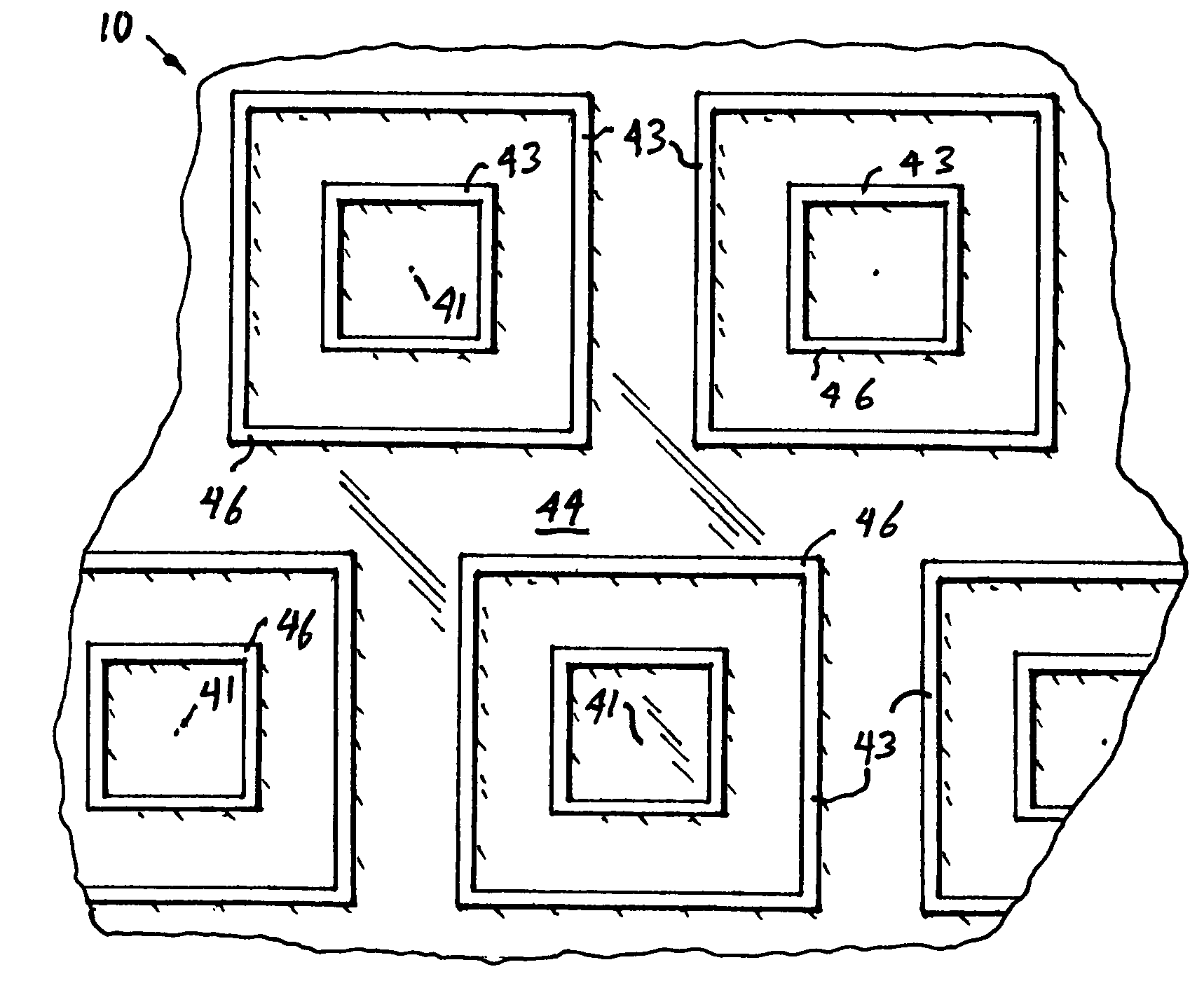
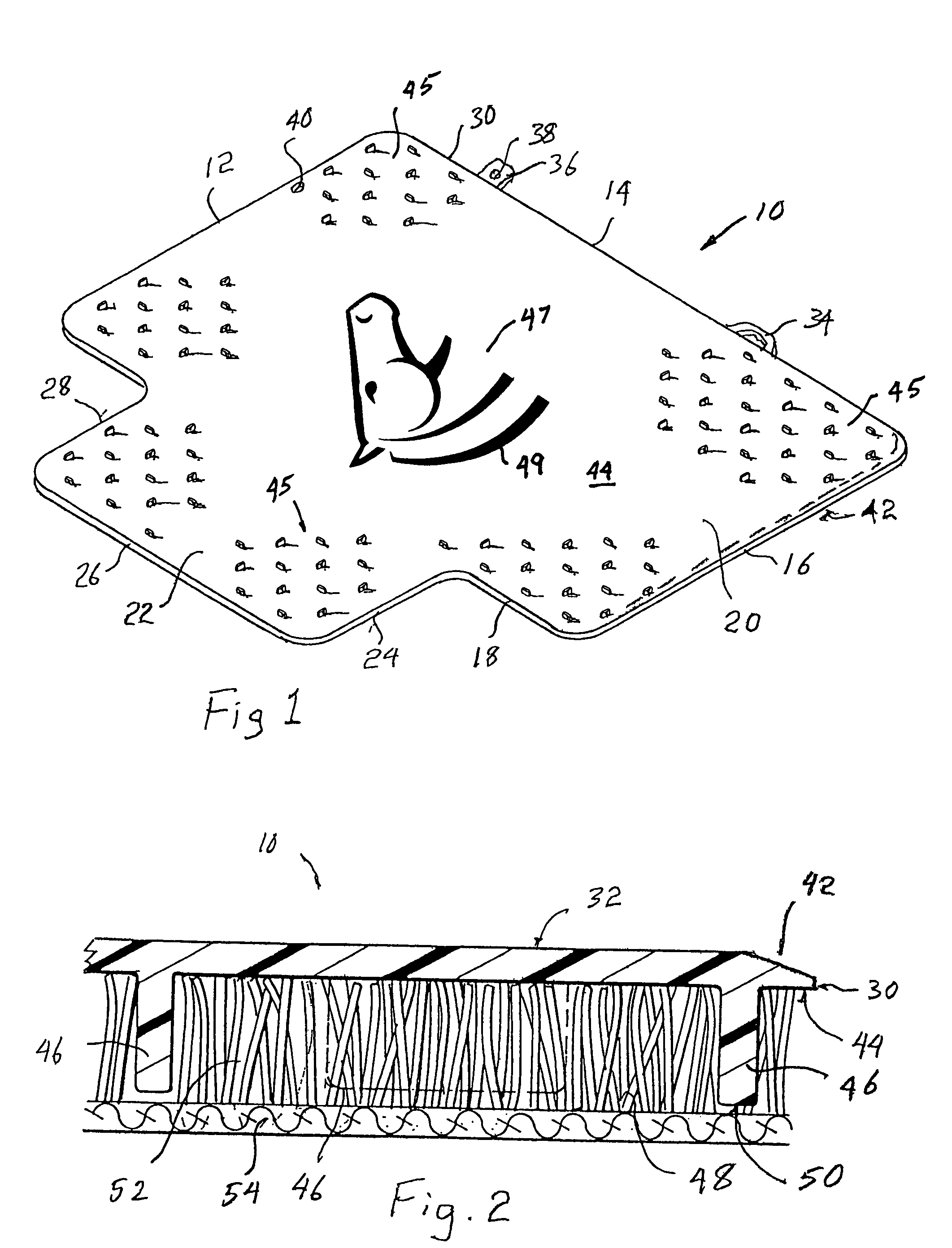
[0026]FIG. 1 shows a desk chair mat 10 formed of a planar, semi-rigid member (made from, e.g., PVC, polypropylene, semi-rigid vinyl or other suitable material) having four side edges 12, 14, 16 and 18, which define a major portion 20 of the chair mat 10. An optional extension portion 22 of the same material and thickness, projects or extends integrally from side edge 18, and is further defined by edges 24, 26, 28 completing the periphery 30 of the mat 10. The extension 22, as is well known, is designed to project into the well area of a desk (not shown), with the remainder of the chair mat 10 behind the desk and serving as the principal contact area for a desk chair (not shown) typically (but not necessarily) fitted with rollers or casters. The chair mat 10 for purposes of this invention, however, need not have an extension 22 of this type. The chair mat 10 can include one or more handles 34, which can project from any point on the periphery 30 of the mat 10. The chair mat 10 can al...


PUM

PropertyMeasurementUnit
aspect ratioaaaaaaaaaa
areaaaaaaaaaaa

Abstract

A desk chair mat has a substantially planar upper surface suitable for interaction with a chair support structure, a perimeter defining an outer edge of the mat, a lower surface parallel to the upper surface. An array of generally blunt projections extends downwardly from a first area of the lower surface for engagement with a carpet. An image is formed within a second area of the lower surface. Each blunt projection has a smooth end surface spaced below the lower surface by a distance sufficient to penetrate into the carpet pile. The array is generally a regular pattern of the projections that can be arranged at an angle with respect to each nearest neighbor to provide enhanced resistance to lateral movement of the mat with respect to the carpet to protect the image from abrasion.

Description

CROSS-REFERENCE TO RELATED APPLICATIONS[0001]The present invention is a continuation-in-part of U.S. application Ser. No. 10 / 439,691 filed May 16, 2003, now U.S. Pat. No. 6,946,184.BACKGROUND[0002]The present invention is directed to chair mats and specifically, to chair mats typically used under desk chairs in order to protect an underlying carpet. In particular, the present invention relates to a chair mat having a decorative pattern and on which a chair, such as a desk chair, may be used without harming the decorative pattern.[0003]Desk chair mats for office and home use are well known. Such a chair mat has a main portion on which the desk chair rolls, and can include a forward lip portion which is adapted to extend partially into a desk well, and on which the feet of the person sitting in the chair can rest. A desk chair mat that is to be applied over carpeting is typically formed of a semi-rigid plastic, and has an array of short, sharp spikes on an underside thereof, which hol...

Claims


Application Information

Patent Timeline
Patent Type & Authority Patents(United States)
IPC IPC(8): B32B3/26B32B3/06B32B7/08
CPCB32B3/06B32B7/08Y10T428/24182Y10T428/24479A47G27/0206
Inventor ROBBINS, III, EDWARD S.
Owner ROBBINS III EDWARD S
Why Eureka
Try Eureka