
Average current-mode feedback control of multi-channel class-d audio amplifier

a multi-channel classd, audio amplifier technology, applied in the direction of amplifier combinations, low frequency amplifiers, frequency response correction, etc., can solve the problems of unanswered questions about such use, no known knowledge or evidence from known usages of current-mode control

Active Publication Date: 2016-12-22
CRESTRON ELECTRONICS
View PDF3 Cites 6 Cited by
  • Summary
  • Abstract
  • Description
  • Claims
  • Application Information

AI Technical Summary

Benefits of technology

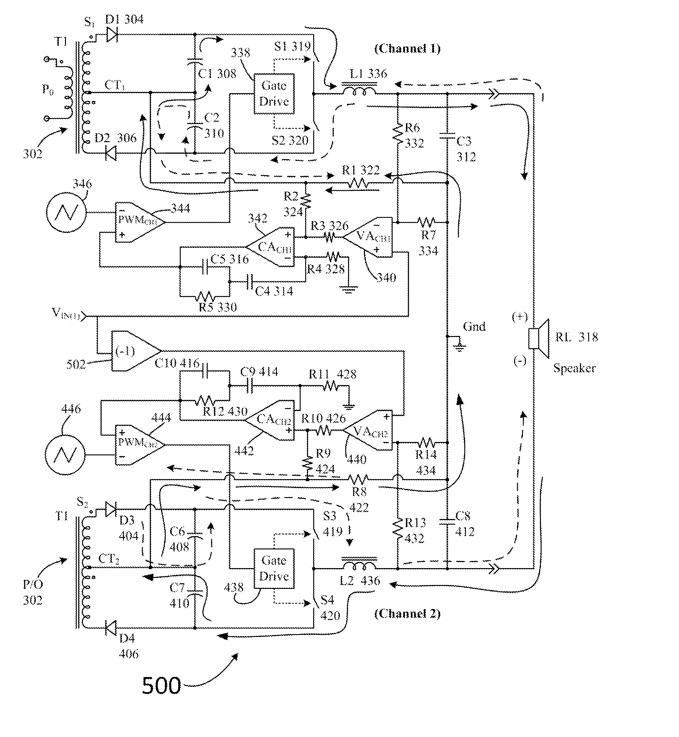
The patent text describes a circuit that reduces errors and maintains high efficiency in controlling the output of an audio amplifier. This is achieved through the use of current-mode control circuitry and voltage-mode control circuitry, which work together to minimize errors and maintain high loop gain over a wide range of frequencies. The expected audio frequency range is from 20 Hz to 20,000 Hz. The technical effect of this invention is to provide a more accurate and efficient means of controlling the output of an audio amplifier, resulting in improved sound quality and reduced errors.

Problems solved by technology

This feedback loop design task is especially difficult when the loop is closed at the output of the audio amplifier channel, after the L-C filter.
This is made very difficult by the presence of the double-pole characteristic of the typical L-C output filter that is a part of most high-fidelity Class-D audio amplifier topologies.
However, many questions about such use remain unanswered, specifically, exactly how the current-mode control is implemented, whether peak current-mode control or average current-mode control is used, or how, and where, the current sensing signal is detected and processed.
Further, there is no known knowledge or evidence from known usages of current-mode control in Class-D audio amplifiers about the suitability of the stated method of double-loop control in regard to multi-channel audio amplifier designs, in which it is desired to connect two independent channels in a BTL configuration.

Method used


Image

  • Average current-mode feedback control of multi-channel class-d audio amplifier
  • Average current-mode feedback control of multi-channel class-d audio amplifier
  • Average current-mode feedback control of multi-channel class-d audio amplifier

Examples


Embodiment Construction

[0043]The embodiments are described more fully hereinafter with reference to the accompanying drawings, in which embodiments of the inventive concept are shown. In the drawings, the size and relative sizes of layers and regions may be exaggerated for clarity. Like numbers refer to like elements throughout. The embodiments may, however, be embodied in many different forms and should not be construed as limited to the embodiments set forth herein. Rather, these embodiments are provided so that this disclosure will be thorough and complete, and will fully convey the scope of the inventive concept to those skilled in the art. The scope of the embodiments is therefore defined by the appended claims. The detailed description that follows is written from the point of view of a control systems company, so it is to be understood that generally the concepts discussed herein are applicable to various subsystems and not limited to only a particular controlled device or class of devices, such as...


PUM


Abstract

Described herein are several configurations of Class-D audio amplifiers, including a single-ended and a bridge-tied load (BTL) configuration, in which voltage-mode control and average current-mode control circuitry in feedback loops can be included to control the outputs of the Class-D amplifier to reduce open-loop errors and maintain a relatively high loop gain over an expected audio frequency range. The average current-mode control circuitry monitors current through a resistor common to both a current flow into a positive terminal of a loudspeaker associated with the amplifier and a current flow into a negative terminal of the loudspeaker. The voltage-mode control circuitry works with the average current-mode control circuitry in controlling the output of the Class-D audio amplifier.

Description

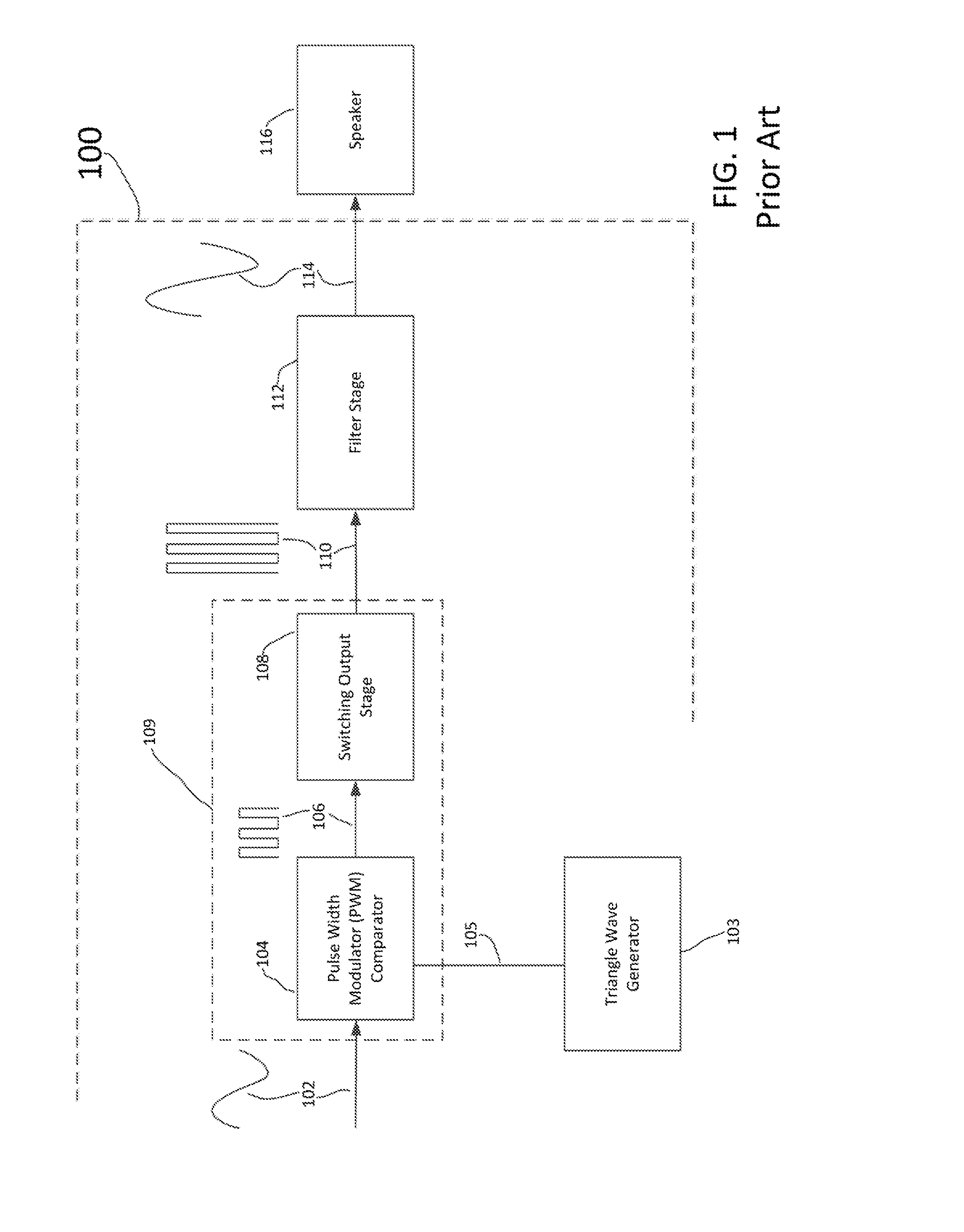
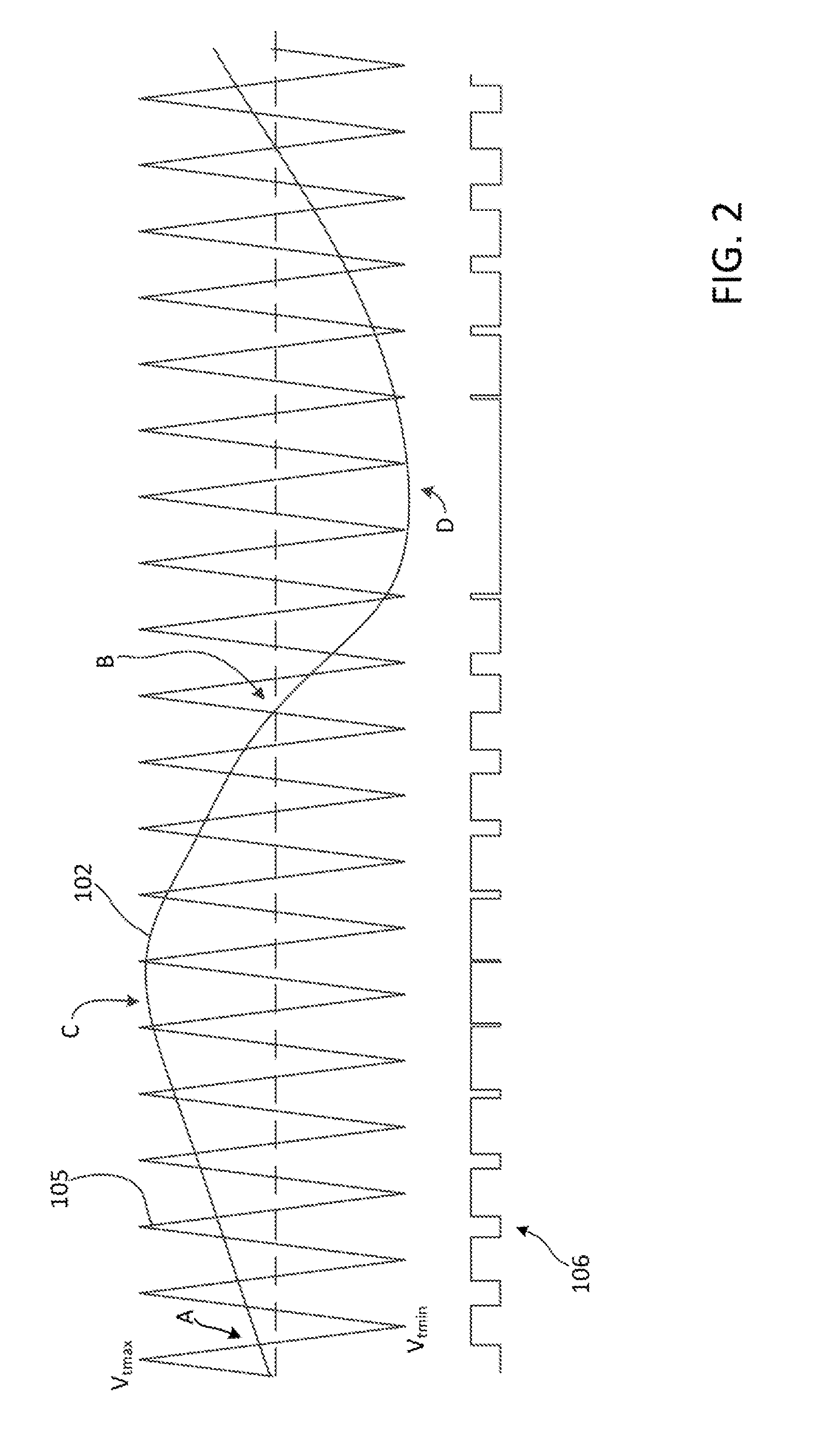
PRIORITY INFORMATION[0001]The present application claims priority under 35 U.S.C. §119(e) to U.S. Provisional Patent Application Ser. No. 62 / 181,370, filed 18 Jun. 2016, the entire contents of which are expressly incorporated herein by reference.BACKGROUND[0002]Technical Field[0003]Aspects of the embodiments relate to use of current-mode feedback control of a multi-channel Class-D audio amplifier.[0004]Background Art[0005]Typically one of the last components in an audio distribution chain, audio amplifiers amplify a low power audio signal to a level suitable for driving one or more loudspeakers. Multi-channel audio amplifiers are employed throughout structures to amplify more than one channel of audio.[0006]As known to those of skill in the art, typical Class-D audio amplifiers are a class of audio amplifier in which the audio signal modulates a pulse width modulated carrier signal to drive the output. Referring now to FIG. 1, a block diagram of class-D audio amplifier 100 is illust...

Claims


Application Information

Patent Timeline
Patent Type & Authority Applications(United States)
IPC IPC(8): H03F3/217H04R3/04H04R3/02H03F3/183H03F1/34
CPCH03F3/2173H03F3/183H03F2200/351H04R3/02H04R3/04H03F1/34H03F3/68H03F2200/03
Inventor BUONO, ROBERT
Owner CRESTRON ELECTRONICS
Learn More