

Sealed honeycomb structure
a honeycomb and sealing technology, applied in the field of sealed honeycomb structure, can solve the problems of deterioration of the sealing performance of the honeycomb structure, and deterioration of the purification performance of the exhaust gas, so as to reduce the influence of pressure loss, and suppress the increase of pressure loss
- Summary
- Abstract
- Description
- Claims
- Application Information
AI Technical Summary
Benefits of technology
Problems solved by technology
Method used
Image

Examples
example 1
[0100]Cordierite material (alumina, talc, and kaolin) is used as the ceramic material. Mass ratio of alumina, talc, and kaolin is a mass ratio obtained after burning. Ceramic mold material is obtained by mixing the ceramic material with the binder (methylcellulose) and water. The obtained ceramic mold material is kneaded by using the kneader so as to obtain the body.
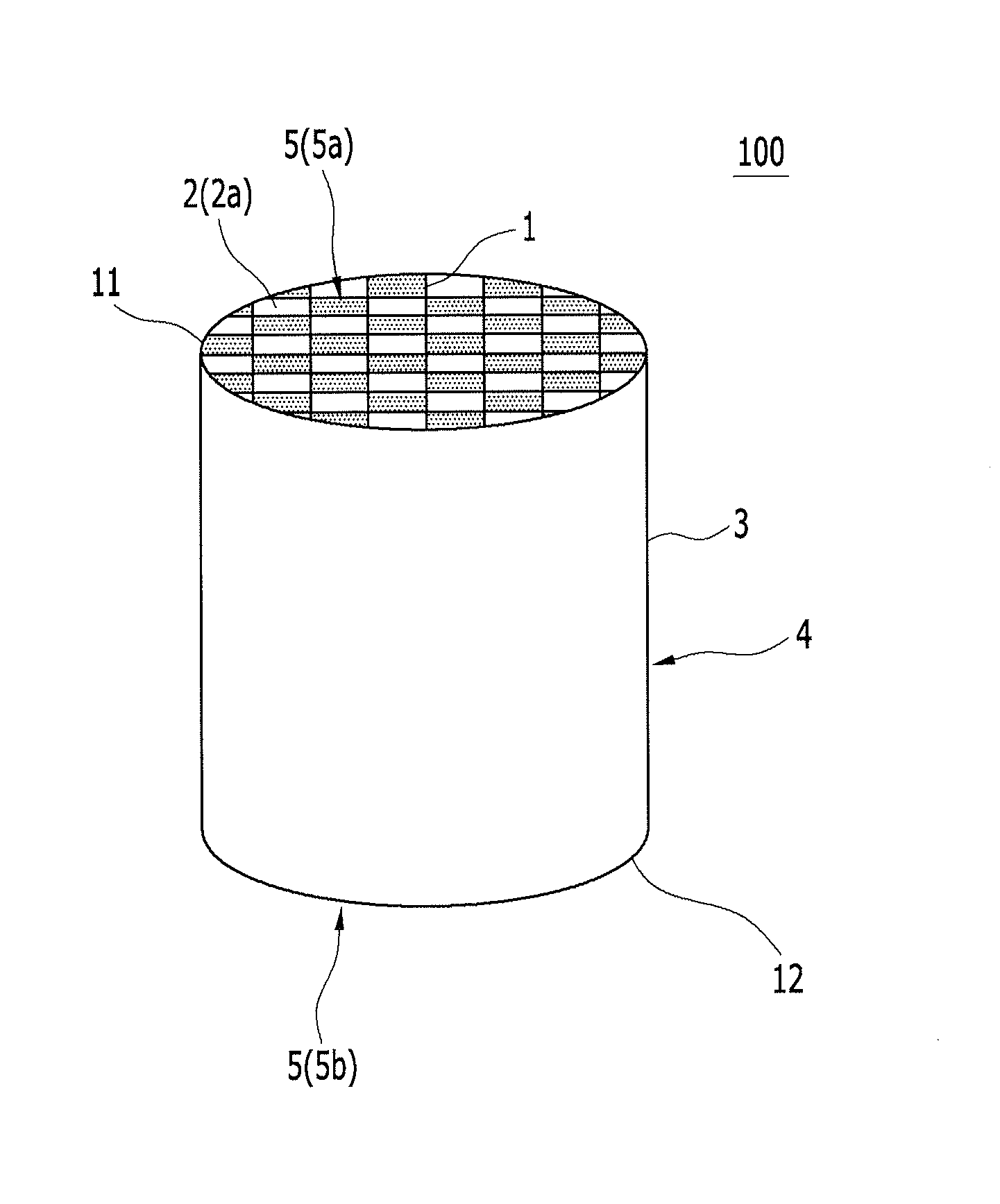
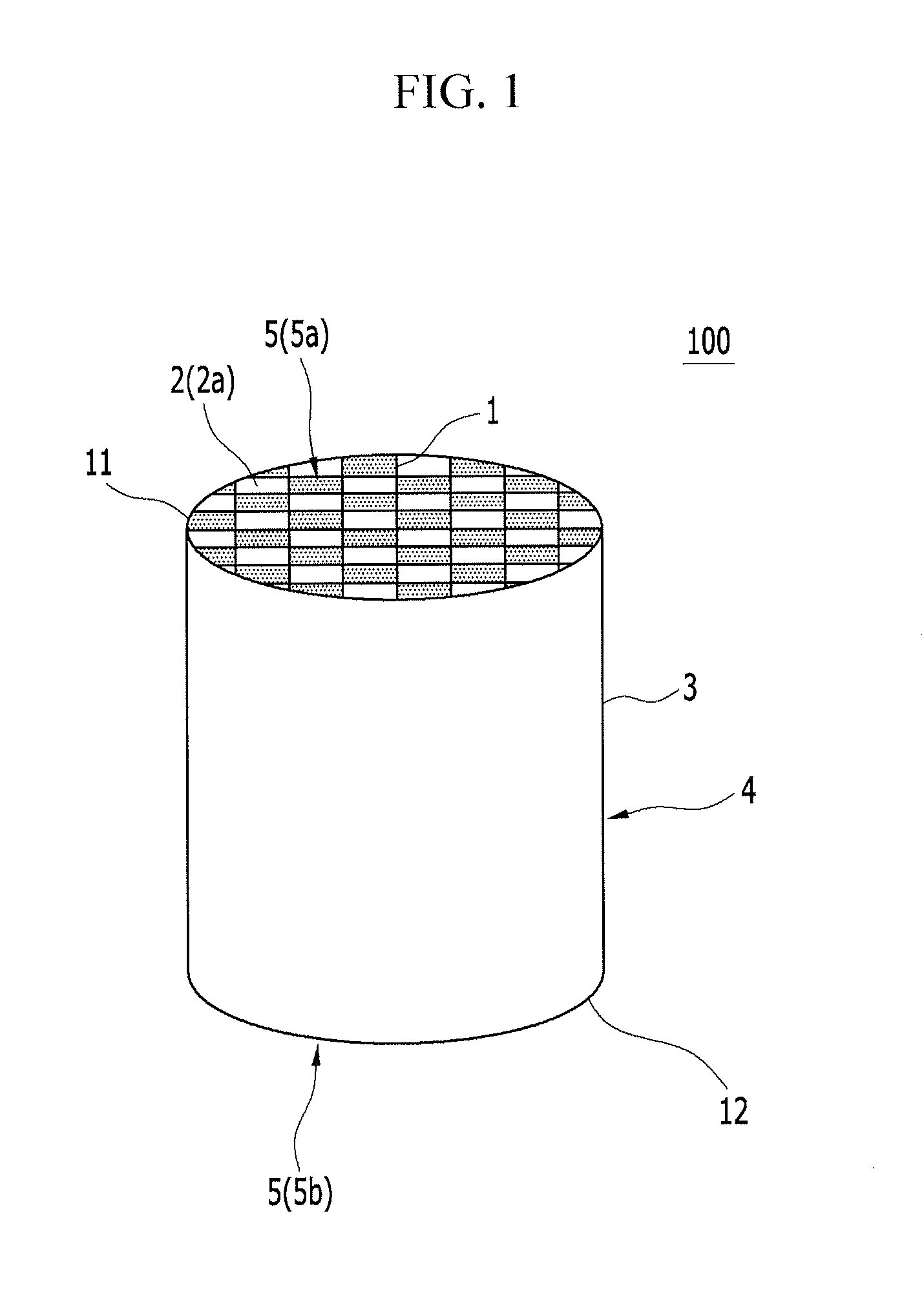
[0101]After that, the molded article of the honeycomb is formed by molding the body by means of a vacuum extruder. Wall thickness is 0.305 mm, cell density is 46.5 cell / cm2, and cell pitch is 1.47 mm in the honeycomb structure obtained by burning the molded article of the honeycomb. In addition, entire shape (entire shape after burning) of the molded article of the honeycomb is cylindrical (diameter of the end surface is 143.8 mm, and a length in the extending direction of the cell is 152.4 mm). The entire shape of the molded article of the honeycomb is integrally formed (monolithic structure), and this honeycomb structu...
examples 2 to 7 and 9 to 13
and Comparative Examples 1 to 3
[0119]The sealed honeycomb structure is manufactured by the same method manufacturing Example 1 except that the wall thickness, the cell pitch and the cell where the reinforced part is formed (whether the reinforced part exists or not) in the honeycomb structure are changed as shown in Table 1, and the intersection ratio (L / T) of the inlet cell and the intersection ratio (L / T) of the outlet cell are changed as shown in Table 1. In addition, Example 13 shows that the reinforced parts are formed at a part of the outlet cells and the inlet cells. The same tests as Example 1 are done on the obtained sealed honeycomb structure. The results are shown in Table 2. In addition, the “soot mass limits (SMLs)” of Examples 1, 8, 9, 12 and 13 and Comparative Examples 1 and 4 are detected.
example 8
[0120]Carbonization silicon (SiC) is used as the ceramic material so as to manufacture the honeycomb segment, and the honeycomb structure of segment type is manufactured by bonding sixteenth honeycomb segments. In detail, SiC powder and Si metal power are mixed in a mass ratio of 80:20, and methyl cellulose and hydroxypropoxy methylcellulose as the binder, starch and water-absorbent resin as the pore-forming material, surfactant and water are mixed to the mixture of SiC powder and Si metal power such that the ceramic mold material is obtained. The obtained ceramic mold material is kneaded by using kneader such that the body is obtained.
[0121]The molded article of honeycomb is formed by molding the body by means of the vacuum extruder. The wall thickness of the molded article of the honeycomb is 305 μm, the cell density of the molded article of the honeycomb is 46.5 cell / cm2, and the cell pitch of the molded article of the honeycomb is 1.47 mm in the honeycomb structure. In addition,...
PUM
| Property | Measurement | Unit |
|---|---|---|
| thickness | aaaaa | aaaaa |
| thickness | aaaaa | aaaaa |
| thickness | aaaaa | aaaaa |
Abstract
Description
Claims
Application Information