Electro-hydraulic brake system including isolated circuits and method of controlling the same

a technology of electrohydraulic brakes and isolated circuits, applied in the direction of braking systems, braking components, transportation and packaging, etc., can solve the problems of insufficient oil quantity capable of braking, insufficient braking force, and insufficient oil quantity, etc., to secure braking stability, braking force and a braking

Active Publication Date: 2016-12-29
HYUNDAI MOTOR CO LTD
View PDF3 Cites 14 Cited by
  • Summary
  • Abstract
  • Description
  • Claims
  • Application Information

AI Technical Summary

Benefits of technology

[0026]The present invention guarantees braking stability of an electro-hydraulic brake system even if leakage is generated in a circuit of the electro-hydraulic brake system and oil leaks.
[0038]According to the present invention, it is possible to completely isolate a plurality of circuits constituting the electro-hydraulic brake system, so that even when oil leaks in some circuits, it is possible to sufficiently secure an oil quantity enabling braking in the case of an emergency by preventing oil of the respective circuits from being mixed.
[0039]Accordingly, it is possible to sufficiently secure braking force and a braking distance by the normally operated isolated circuit and a pressure generating unit including the motor, thereby securing braking stability when leakage is generated.

Problems solved by technology

Accordingly, when the pressure generating unit 30 is continuously operated, there is a problem in that an oil quantity required for braking is insufficient due to continuous oil leakage at a leak point.
An oil quantity for operating the motor is insufficient due to the continuous oil leakage, and the oil of the oil reservoir 10 is sucked through the oil return line 50, so that the pressure generating unit cannot operate the motor, thereby failing to sufficiently provide braking force.
That is, even though the control unit detects that it is impossible to operate the motor, switches an operation mode into an oil leakage detection mode, and performs braking only with the backup master cylinder by opening the cut valves, an oil quantity capable of performing braking eventually becomes insufficient, so that it is impossible to perform braking.
Further, braking force is formed only with a pedal effort of a driver, so that a problem in safety, such as an increase of a braking distance, is caused.

Method used


Image

  • Electro-hydraulic brake system including isolated circuits and method of controlling the same
  • Electro-hydraulic brake system including isolated circuits and method of controlling the same
  • Electro-hydraulic brake system including isolated circuits and method of controlling the same

Examples


Embodiment Construction

[0052]Hereinafter reference will now be made in detail to various embodiments of the present invention, examples of which are illustrated in the accompanying drawings and described below. While the invention will be described in conjunction with exemplary embodiments, it will be understood that the present description is not intended to limit the invention to those exemplary embodiments. On the contrary, the invention is intended to cover not only the exemplary embodiments, but also various alternatives, modifications, equivalents and other embodiments, which may be included within the spirit and scope of the invention as defined by the appended claims.

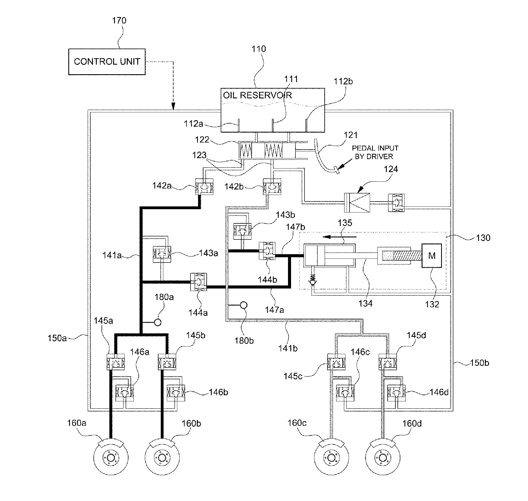
[0053]The present invention relates to an electro-hydraulic brake (EHB) system, and is a technology applicable to an EHB system capable of collectively implementing a general braking function and functions such as an anti-brake system (ABS) function and an electronic stability control (ESC).

[0054]Particularly, an EHB system including ...


PUM


Abstract

Disclosed are electro-hydraulic brake system and control method. The system may include a braking input unit to provide a braking input according to an operation of a driver, a control unit to control generation of braking oil pressure according to the braking input of the braking input unit, a pressure generating unit to generate the braking oil pressure, wheel clamping units to generate braking forces to corresponding wheels, and oil supply lines to transfer the braking oil pressure to corresponding wheel clamping units. Each oil supply line is fluidly connected to the pressure generating unit. For each oil supply line, a split valve is installed in a connection portion of the pressure generating unit and the oil supply line. When the split valve is closed, the split valve blocks the braking oil pressure supplied from the pressure generating unit to the oil supply line.

Description

CROSS-REFERENCE TO RELATED APPLICATION[0001]The present application claims priority of Korean Patent Application Number 10-2015-0089025 filed Jun. 23, 2015, the entire contents of which application are incorporated herein for all purposes by this referenceBACKGROUND[0002]Technical Field[0003]The present disclosure relates to an electro-hydraulic brake system and a method of controlling the same. More particularly, it relates to an electro-hydraulic brake system, which generates required oil pressure with a motor according to braking performed by a driver and transmits the generated oil pressure to a wheel brake, and a method of controlling the same.[0004]Background Art[0005]Recently, a brake-by-wire technology adopting an electronic control system for control has been applied to a brake system of a vehicle, instead of an existing known general hydraulic control system.[0006]The electronic control brake system generates required oil pressure by using an electric motor according to br...

Claims


Application Information

Patent Timeline
Patent Type & Authority Applications(United States)
IPC IPC(8): B60T17/22B60T8/40B60T13/68
CPCB60T17/221B60T2270/82B60T8/4081B60T13/686B60T13/745B60T7/042B60T13/166B60T13/662
Inventor JUNG, YOUNG SUK
Owner HYUNDAI MOTOR CO LTD
Why Eureka
Try Eureka