Modular wind turbine rotor blades and methods of assembling same

a technology of wind turbines and rotor blades, applied in the field of wind turbine rotor blades, can solve the problems of wind turbines that are not designed to withstand, rotor blades are not without problems, and the wind turbine is damaged and catastrophically damaged

Inactive Publication Date: 2016-12-29
GENERAL ELECTRIC CO
View PDF8 Cites 51 Cited by
  • Summary
  • Abstract
  • Description
  • Claims
  • Application Information

AI Technical Summary

Benefits of technology

[0010]In one embodiment, the rotor blade may also include at least one pressure side segment and at least one suction side segment. In another embodiment, the blade root section may include one or more spar caps extending in a generally span-wise direction. Similarly, the blade tip section may include one or more corresponding spar caps extending in a generally span-wise direction. Thus, in certain embodiments, the blade root section and the blade tip section may be joined together via their respective spar cap(

Problems solved by technology

Further, the pressure and suction shells are relatively lightweight and have structural properties (e.g., stiffness, buckling resistance and strength) which are not configured to withstand the bending moments and other loads exerted on the rotor blade during operation.
Such rotor blades, however, are not without issues.
These bonding lines are a critical design constraint of the blades as a significant number of turbine blade field failures occur at the bond-line.
Separation of the bond line along the leading and/or trailing edges of an operational turbine blade can result in a catastrophic failure and damage to the wind turbine.
In addition, the methods used to manufacture the rotor blades and/or structural components thereof can be difficult to control, defect prone, and/or highly labor intensive due to handling of the dry fabrics and the challenges of infusing large laminated structures.
Moreover, as rotor blades continue to increase in size, convent

Method used


Image

  • Modular wind turbine rotor blades and methods of assembling same
  • Modular wind turbine rotor blades and methods of assembling same
  • Modular wind turbine rotor blades and methods of assembling same

Examples


Embodiment Construction

[0039]Reference now will be made in detail to embodiments of the invention, one or more examples of which are illustrated in the drawings. Each example is provided by way of explanation of the invention, not limitation of the invention. In fact, it will be apparent to those skilled in the art that various modifications and variations can be made in the present invention without departing from the scope or spirit of the invention. For instance, features illustrated or described as part of one embodiment can be used with another embodiment to yield a still further embodiment. Thus, it is intended that the present invention covers such modifications and variations as come within the scope of the appended claims and their equivalents.

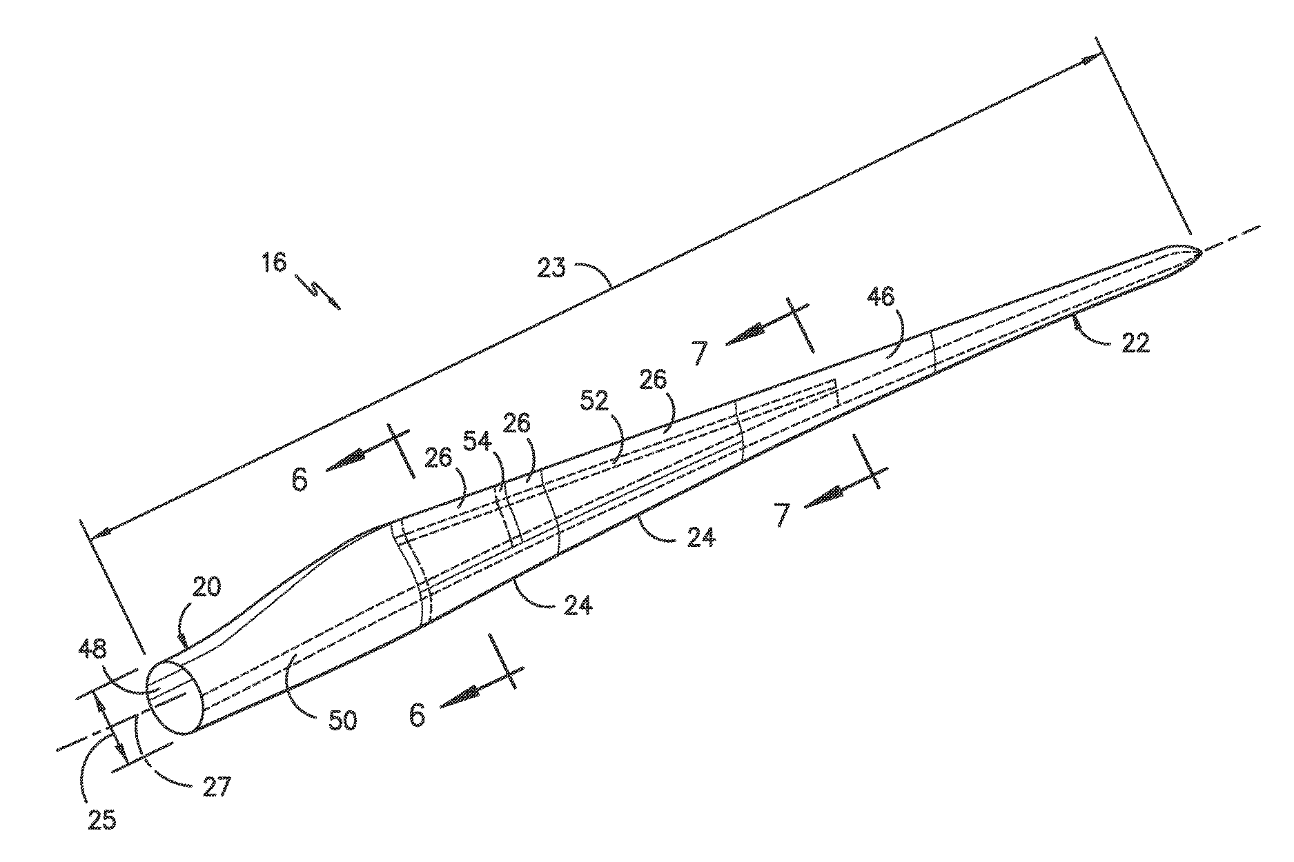
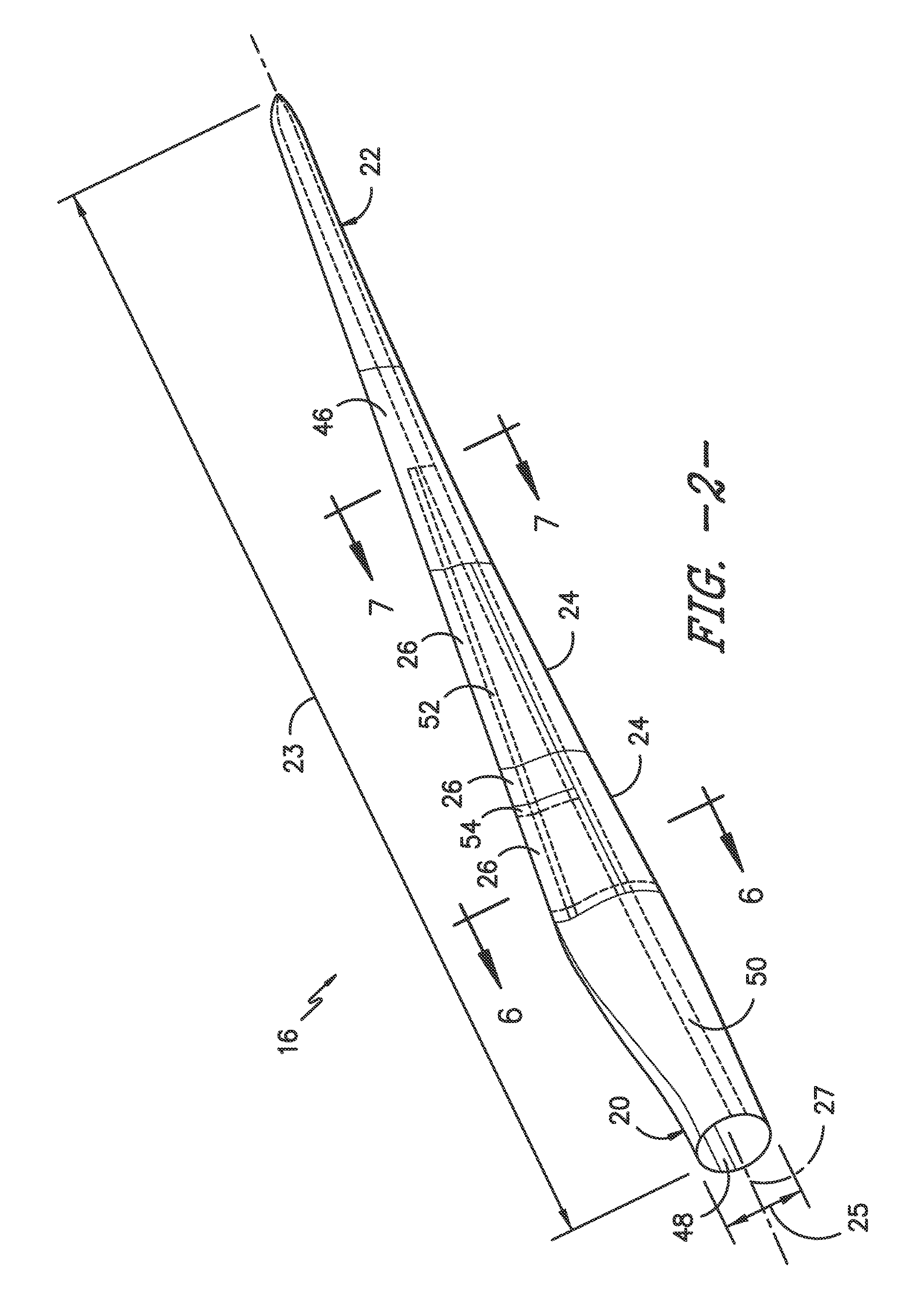
[0040]Generally, the present disclosure is directed to a modular rotor blade for a wind turbine and methods of assembling same. In certain embodiments, the rotor blade includes a pre-formed blade root section, a pre-formed blade tip section, and one or more...


PUM

PropertyMeasurementUnit
Pressureaaaaaaaaaa
Adhesivityaaaaaaaaaa

Abstract

The present disclosure is directed to a modular rotor blade for a wind turbine and methods of assembling same. The rotor blade includes a blade root section, a blade tip section, at least one leading edge segment having a forward pressure side surface and a forward suction side surface, and at least one trailing edge segment having an aft pressure side surface and an aft suction side surface. Further, the leading edge segment and the trailing edge segment are arranged between the blade root section and the blade tip section in a generally span-wise direction. In addition, the leading edge segment and the trailing edge segment are joined at a pressure side seam and a suction side seam.

Description

FIELD OF THE INVENTION[0001]The present disclosure relates generally to wind turbine rotor blades, and more particularly to modular wind turbine rotor blades and methods of assembling same.BACKGROUND OF THE INVENTION[0002]Wind power is considered one of the cleanest, most environmentally friendly energy sources presently available, and wind turbines have gained increased attention in this regard. A modern wind turbine typically includes a tower, a generator, a gearbox, a nacelle, and a rotor having a rotatable hub with one or more rotor blades. The rotor blades capture kinetic energy of wind using known airfoil principles. The rotor blades transmit the kinetic energy in the form of rotational energy so as to turn a shaft coupling the rotor blades to a gearbox, or if a gearbox is not used, directly to the generator. The generator then converts the mechanical energy to electrical energy that may be deployed to a utility grid.[0003]The rotor blades generally include a suction side shel...

Claims


Application Information

Patent Timeline
IPC IPC(8): F03D1/06
CPCF03D1/0675F05B2240/302F05B2280/4007Y02E10/72
Inventor CARUSO, CHRISTOPHER DANIELYARBROUGH, AARON A.HYNUM, DANIEL ALANTOBIN, JAMES ROBERT
Owner GENERAL ELECTRIC CO
Why Eureka
Try Eureka