Machining apparatus

Active Publication Date: 2016-12-29
CUTLAND JAPAN
View PDF0 Cites 3 Cited by
  • Summary
  • Abstract
  • Description
  • Claims
  • Application Information

AI Technical Summary

Benefits of technology

[0013]The machining apparatus including the differential device can output torque from two places, namely, the main gear and the free gear when the first drive unit is driven, and from this state, when the second drive unit is driven, rotational speed of the free gear can be controlled freely. Further, as revolution torque of the planetary gear is transmitted to the free gear, reduced torque is transmitted from the mai

Problems solved by technology

Moreover, particularly when a bevel gear is used in the differential device, a ge

Method used


Image

  • Machining apparatus
  • Machining apparatus
  • Machining apparatus

Examples


Example

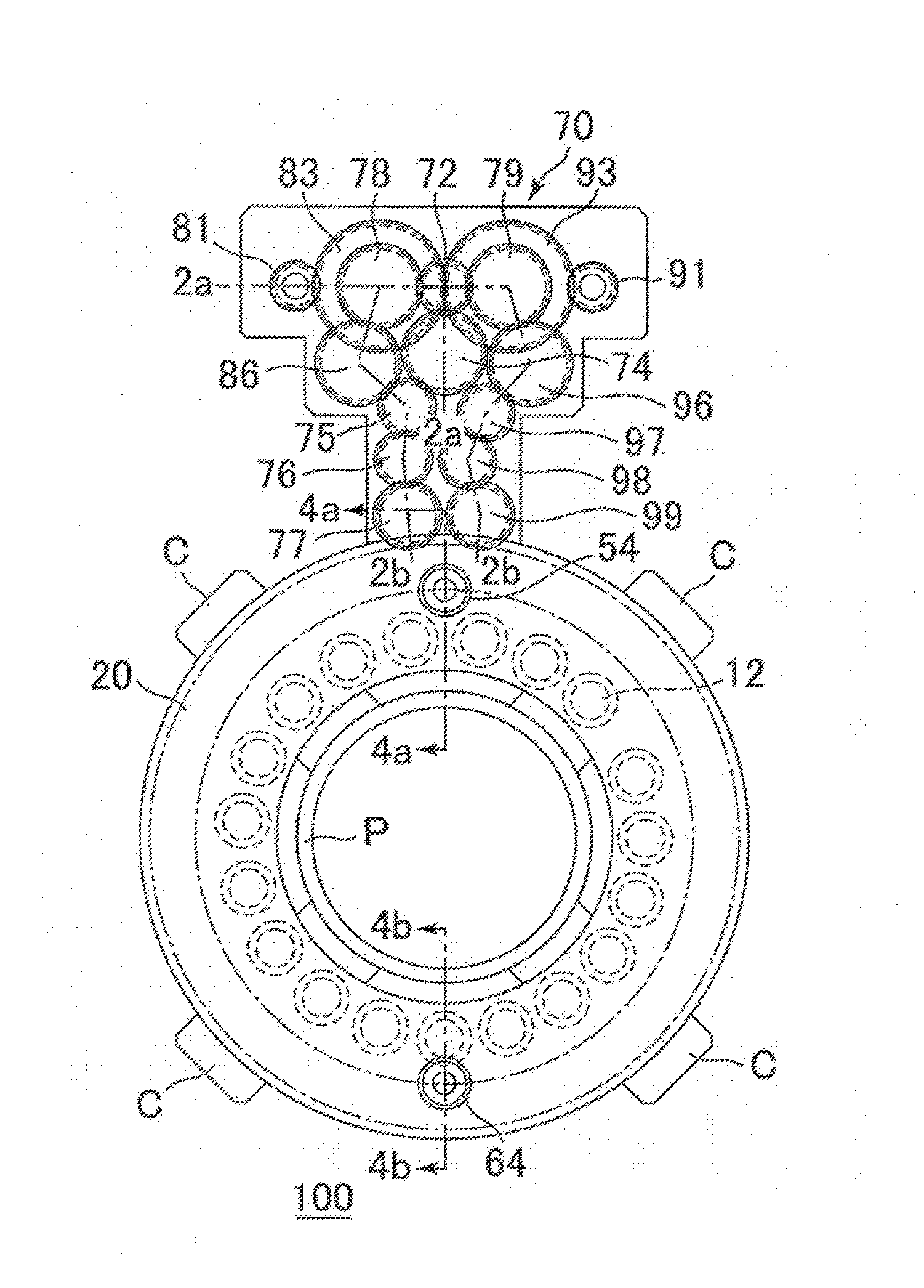
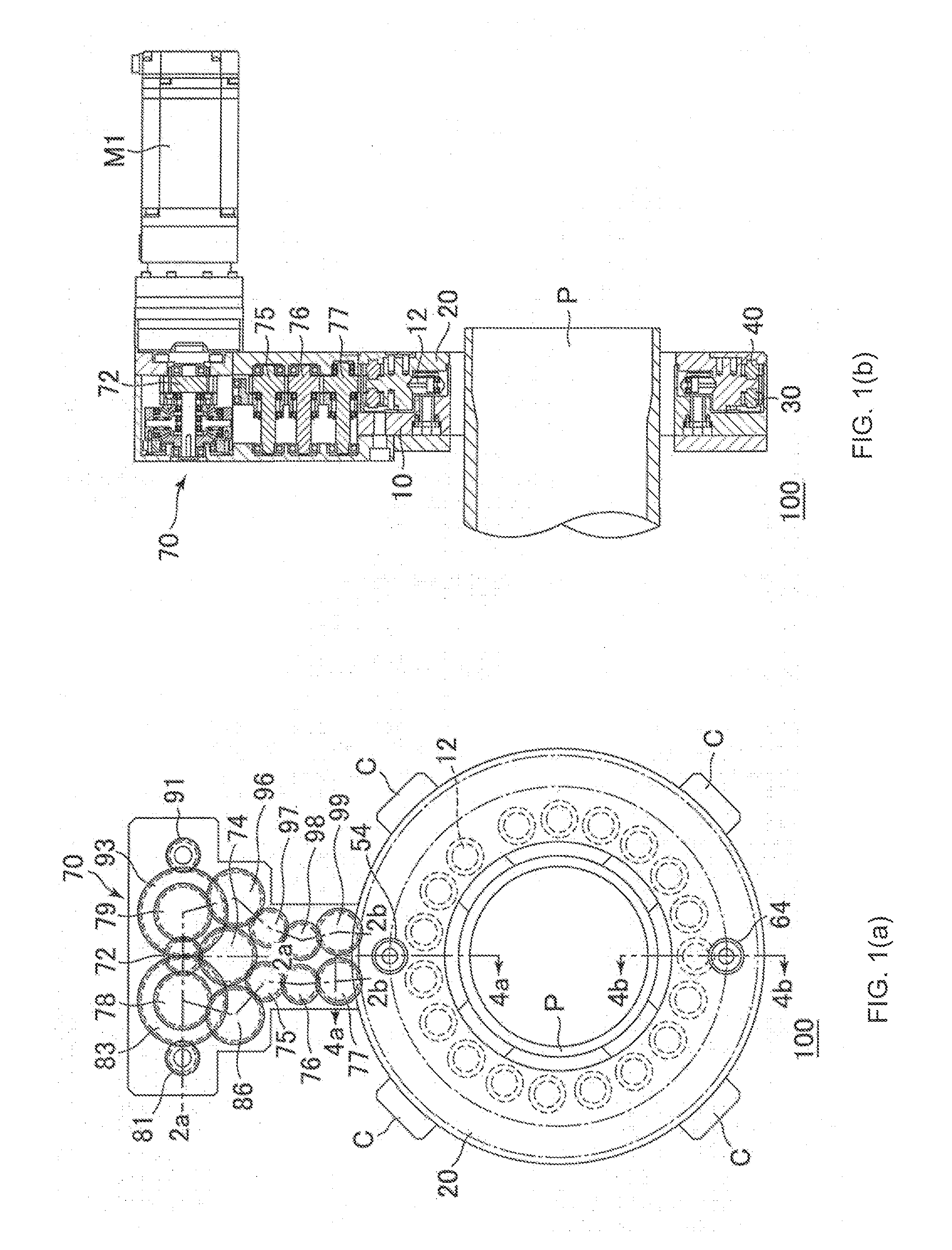
[0028]Following is a description by way of example only with reference to FIGS. 1 to 8 of embodiments of the present disclosure. Still, the present disclosure is not limited to these embodiments.

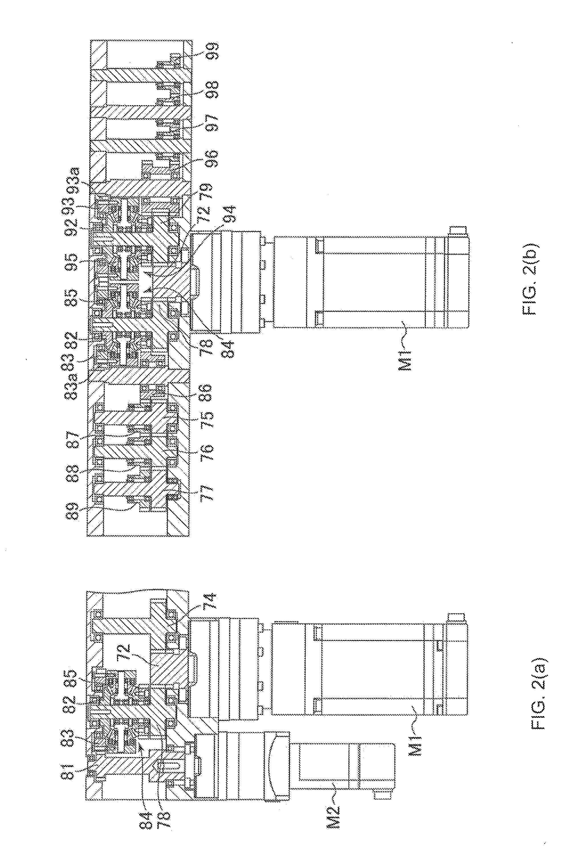
[0029]As shown in FIGS. 1(a) and 1(b), a machining apparatus 100 of the present disclosure includes a housing 10, a face plate 20 and a differential device 70. The differential device 70 includes a motor M1, which serves as a first drive unit, a motor M2, which serves as a second drive unit and a motor M3, which serves as a third drive unit (see FIG. 5). Even without the differential device 70, torque of the motors M1 to M3 can be transmitted respectively to first and second ring gears 30, 40 and the face plate 20. However, the machining apparatus 100 may preferably include the differential device 70, as will be described later, enabling the face plate 20 and the first and second ring gears 30, 40 to rotate by driving the motor M1 only. For convenience, an illustration of the motors M1 to M3...


PUM

PropertyMeasurementUnit
Diameteraaaaaaaaaa
Torqueaaaaaaaaaa

Abstract

A differential device including a planetary gear mechanism having a sub-gear, an annular gear and a planetary gear is more compact than a differential gear using a bevel gear mechanism. Since revolution torque of the planetary gear is transmitted to a free gear, and torque from the main gear is reduced to be transmitted, the differential device can use a small-sized drive unit in comparison with a conventional one. Hence, a machining apparatus including such a differential device is also compact. If the machining apparatus has three drive units, a pair of ring gears, first and second power transmission shafts, a radial movement mechanism and an axial movement mechanism, a tool holder, namely, a tool coupled to the radial movement mechanism and the axial movement mechanism, can be freely moved in axial and radial directions with respect to the pipe.

Description

FIELD OF THE INVENTION[0001]The present disclosure relates to a machining apparatus for machining (including welding) of a workpiece, or specifically piping (pipe), using a differential device that outputs torque to a plurality of objects by driving one drive unit, and from this state, generates a differential motion to the torque to the plurality of objects by driving another drive unit. Hereinafter, such differential device may be referred to simply as “differential device”, and such apparatus for machining simply as “machining apparatus”DESCRIPTION OF RELATED ART[0002]An example of a machining apparatus using a differential device is disclosed in Japanese Patent Laid-Open No. 2014-172134.[0003]The machining apparatus disclosed in Japanese Patent Laid-Open No. 2014-172134 is composed of an annular housing, an annular face plate, a ring gear, a tool holder, the differential device and two drive units (motors). This machining apparatus, configured to sandwich a pipe with a plurality...

Claims


Application Information

Patent Timeline
IPC IPC(8): F16H48/08B23K37/02
CPCF16H48/08B23K2201/10B23K37/0276B23K37/0247B23B3/26B23K37/0217B23K37/027B23B5/163B23K2101/10B23B5/16B23B5/00
Inventor MORI, KENICHI
Owner CUTLAND JAPAN
Why Eureka
Try Eureka