Cooling System

Inactive Publication Date: 2010-09-30
LI LAURA L +2
View PDF5 Cites 2 Cited by
  • Summary
  • Abstract
  • Description
  • Claims
  • Application Information

AI Technical Summary

Benefits of technology

[0021]In accordance with another embodiment of the present disclosure, a non-toxic, energy efficient cooling system is provided. The system comprises liquid air and an insulated container device configured to contain the liquid air and to maintain the liquid air in its liquefied form. The system further comprises an outlet, and a compressor device configured to introduce gas-form air into the insulated container device, thus causing some of the air in the insulated container device to rise and exit the container device as cooled gas-form air. The compressor device is further configured to push the cooled gas-form air from the container device to the outlet. The compressor device is coupled to the bottom quadrant of the reservoir for the insulated container device. The system further comprises a cooled air conduit configured to provide a conduit without coils for the cooled gas-form air from the insulated container device to the outlet.
[0022]The system still further comprises a fan devic

Problems solved by technology

Air conditioners have certain drawbacks in that they do not consume energy in an efficient manner.
This boil/condense cycle requires a significant amount of energy.
Also, as discussed in greater detail hereinbelow, air conditioners often use refrigerants which are harmful to both the environment and humans.
Although these heat pump systems may be more energy efficient than air conditioners, they still require a significant amount of energy.
Moreover, both heat pump systems and air conditioners suffer from drawbacks in that the refrigerants used in such systems may be damaging to both the environment and humans.
The United States and many other countries have bann

Method used


Image

  • Cooling System
  • Cooling System
  • Cooling System

Examples


Embodiment Construction

[0031]The cooling system of the present disclosure provides for energy efficiency and reduced toxicity to both humans and the environment.

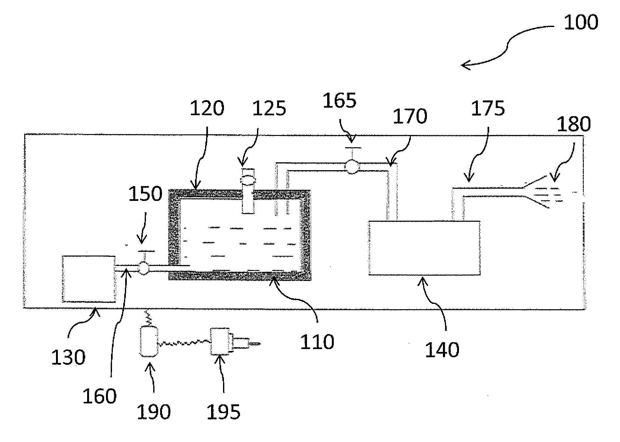
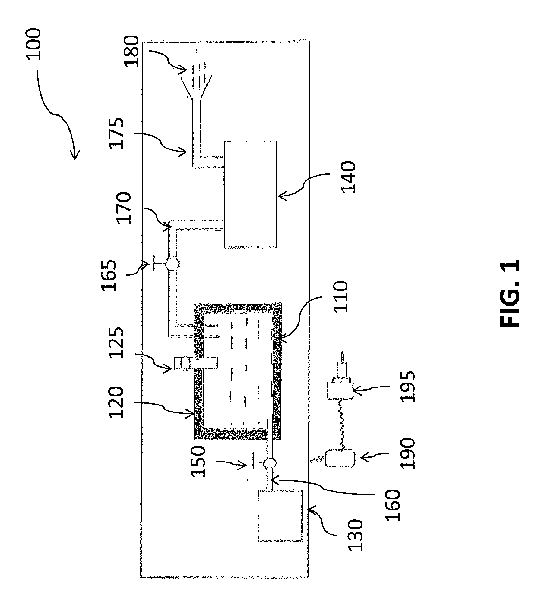
[0032]Referring now to FIG. 1, illustrated is a cooling system 100 in accordance with one embodiment of the present disclosure. As shown, the cooling system 100 comprises liquid air 110 disposed within an insulated container 120.

[0033]Liquid air is everyday air that has been compressed and cooled to an extremely low temperature, thus changing its state from a gas to a liquid. Commercially, liquid air may be obtained through various processes. For example, the ordinary air may be washed in order to remove impurities. This air may also be subjected to lime (also known as calcium oxide) in order to remove the carbon dioxide that is present in today's environment. This gaseous air may be compressed using significant pressure (e.g., 2,500-3,000 pounds per square inch). It may then be cooled, e.g., by passing it through cooled pipes which may be dispose...


PUM


Abstract

An energy efficient cooling system that employs liquid air in order to eliminate potentially harmful effects associated with some refrigerants with regard to both humans and the environment. The system includes an insulated container configured to contain liquid air at the appropriate low temperature so that it can remain in its liquefied state. The system further includes at least one air flow device, which may be a compressor and/or a fan. The system also includes a valve-controlled piping system for moving the cool air to an outlet, such as a duct system. Thereafter, the cool air may be distributed throughout a room, building or other area for which cooling is desired.

Description

BACKGROUND OF THE INVENTION[0001]1. Field of Invention[0002]The present disclosure relates generally to cooling systems and, more particularly, to an energy efficient, environmentally friendly cooling system that provides for a significant range of cooling without the use of harmful refrigerants.[0003]2. Description of Related Art.[0004]Cooling systems, such as air conditioners and heat pumps, are often used in indoor spaces to provide temperature control. Air conditioners remove heat from a space, and cycle the previously warm air back into the space as cooler air. Many air conditioners include a compressor, “hot” coils, “cold” coils and an expansion valve.[0005]When an air conditioner is in operation, the compressor compresses cool gas-form refrigerant, thus causing the refrigerant to become a hot, high-pressure gas. The hot gas traverses the “hot” coils, thus causing the hot gas to dissipate heat, and the gas condenses into a liquid. This liquid traverses an expansion valve, caus...

Claims


Application Information

Patent Timeline
IPC IPC(8): F25B19/00F25D17/06C09K5/00
CPCF25D3/10C09K5/041Y02P20/10
Inventor LI, LAURA L.LI, GUANG SHUNLI, MENG CHU
Owner LI LAURA L
Why Eureka
Try Eureka