Method and system for on-line monitoring electrolytic capacitor condition

a technology of electrolytic capacitors and monitoring systems, applied in chemical analysis using precipitation, instruments, material impedances, etc., can solve the problems of electrolytic capacitors being often the most limiting factors of long-life products, out-of-service conditions for the entire converter, etc., and achieves repeatability, low cost, and sufficient prediction accuracy

Active Publication Date: 2016-12-29
MITSUBISHI ELECTRIC CORP
View PDF7 Cites 9 Cited by
  • Summary
  • Abstract
  • Description
  • Claims
  • Application Information

AI Technical Summary

Benefits of technology

[0011]The present invention aims at providing an electrolytic capacitor condition monitoring system which is low cost, resilient to disturbanc...

Problems solved by technology

Their failure leads to out-of-service condition for the entire converter.
E...

Method used


Image

  • Method and system for on-line monitoring electrolytic capacitor condition
  • Method and system for on-line monitoring electrolytic capacitor condition
  • Method and system for on-line monitoring electrolytic capacitor condition

Examples


Embodiment Construction

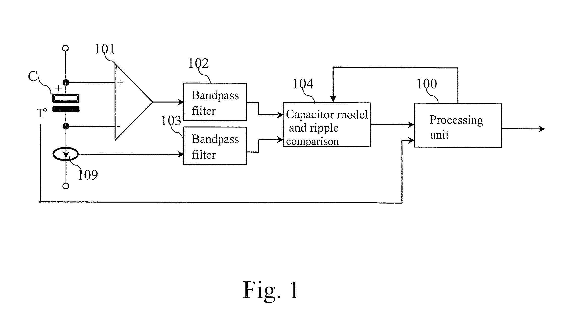
[0077]FIG. 1 represents an example of an architecture of an electrolytic capacitor condition monitoring system according to the present invention.

[0078]The electrolytic capacitor condition monitoring system monitors the equivalent series resistance of an electrolytic capacitor C.

[0079]The electrolytic capacitor condition monitoring system may monitor capacitors having a capacitance value from a few hundred of μF up to a few thousands of μF and a nominal ESR specified around 100 Hz at 20° C. in range of a few dozen of mΩ up to hundreds of mΩ.

[0080]The present invention deduces the state of health of the monitored electrolytic capacitor C from the evolution of its ESR value during its lifetime. Based on an initial value of ESR, the present invention determines an end of life value that corresponds to an aged electrolytic capacitor.

[0081]The electrolytic capacitor C is considered aged when its ESR parameter has increased significantly with respect to its healthy state, i.e. when the es...


PUM


Abstract

A method for on-line monitoring an electrolytic capacitor condition comprising: measuring a voltage ripple across the electrolytic capacitor and the current ripple flowing through the electrolytic capacitor; measuring the temperature of the electrolytic capacitor; emulating the monitored electrolytic capacitor using a capacitor model comprising a capacitor and a solid state adjustable resistor, applying one of the measured ripple to the capacitor model, adjusting the solid state adjustable resistor to minimize the error between an estimated ripple provided by the capacitor model and the other measured ripple not applied to the capacitor model, and estimating an equivalent series resistance of the monitored electrolytic capacitor using value of the solid state adjustable resistor.

Description

BACKGROUND OF THE INVENTION[0001]Field of the Invention[0002]The present invention relates generally to a method and system for on-line monitoring an electrolytic capacitor condition.[0003]Description of the Related Art[0004]In the field of Power Electronics, electrolytic capacitors are known as vulnerable components. Their failure leads to out-of-service condition for the entire converter.[0005]Electrolytic capacitors are often the most limiting factor for long-life products. This is why we observe an increased interest in Condition Monitoring technologies, that permit timely replacement of these components, while disturbance on the service rendered by the equipment is minimised.[0006]Solutions have been proposed to detect ageing of electrolytic capacitors. Usually the ageing detection is made by monitoring the variation of some parameters of the electrolytic capacitor. For example, a reduction of the electrolytic capacitance value may be used to detect the end of life of the elect...

Claims


Application Information

Patent Timeline
IPC IPC(8): G01N27/04G01N27/14
CPCG01N27/14G01N27/041G01R31/64G01N25/18G01N31/02G01R31/396
Inventor MOLLOV, STEFANFOUBE, LAURENT
Owner MITSUBISHI ELECTRIC CORP
Why Eureka
Try Eureka