
Remotely deployable inverse proactive status monitoring and reporting system and method of use

Inactive Publication Date: 2016-12-29
GOODRICH GREG
View PDF27 Cites 6 Cited by
  • Summary
  • Abstract
  • Description
  • Claims
  • Application Information

AI Technical Summary

Benefits of technology

The present invention describes a new remote monitoring system that has several technical benefits. Firstly, the system has a self-healing mechanism where if there is a loss of interconnectivity or interoperability with the remote controllers, the on-site controller automatically initiates steps to recover interconnectivity and interoperability with the remote controllers. Secondly, the system allows multiple tenants to access the shared and hosted computer processing environments, providing greater accessibility to on-site controllers from multiple locations with access authorization and authentication credentials. Lastly, the system integrates local sensors and devices with external devices and can force a hard reboot or power-down function to protect devices, sub-systems and systems from damage or harmful operating conditions.

Problems solved by technology

The problem is that these monitoring devices occasionally lose “sync” with their gateway / relay or the gateway locks up, has some kind of error condition preventing normal operation or stops communicating with the monitoring system altogether.
The internet connectivity device(s) may also error out or drop the circuit.
Any number of conditions may cause normal communications to cease.
The gateways / relays in these systems typically only forward these events and have no ability to store the data until the error condition is corrected.
Additionally, the monitoring systems typically do not monitor themselves to confirm they are receiving data from the devices, they just simply don't log anything when a fault occurs.
This causes inaccurate statistics and momentary non-reporting of equipment or system health which can result is serious complications.
One limitation of the prior art is the difficulty in determining the source and location of each error condition.
For example, an error condition could result if the internet is down, the modem or communication device has an error condition, the gateway has some type of error condition, the devices themselves cannot communicate with the gateway / relay or the actual systems being monitored by the devices have a problem.
Often there is no way to recover from these unknown error conditions without sending someone on-site to assess the situation.
This causes time delays resuming normal operations, can cause companies to miss contractual monitoring obligations, and often results unnecessary expense.
In cases where the monitoring devices are far from the home office (i.e. in another state or country) the cost and time required to send someone to the site can be an expensive option.
Therefore, there remains an unmet need in the field of remote monitoring systems.

Method used


Image

  • Remotely deployable inverse proactive status monitoring and reporting system and method of use
  • Remotely deployable inverse proactive status monitoring and reporting system and method of use
  • Remotely deployable inverse proactive status monitoring and reporting system and method of use

Examples


Embodiment Construction

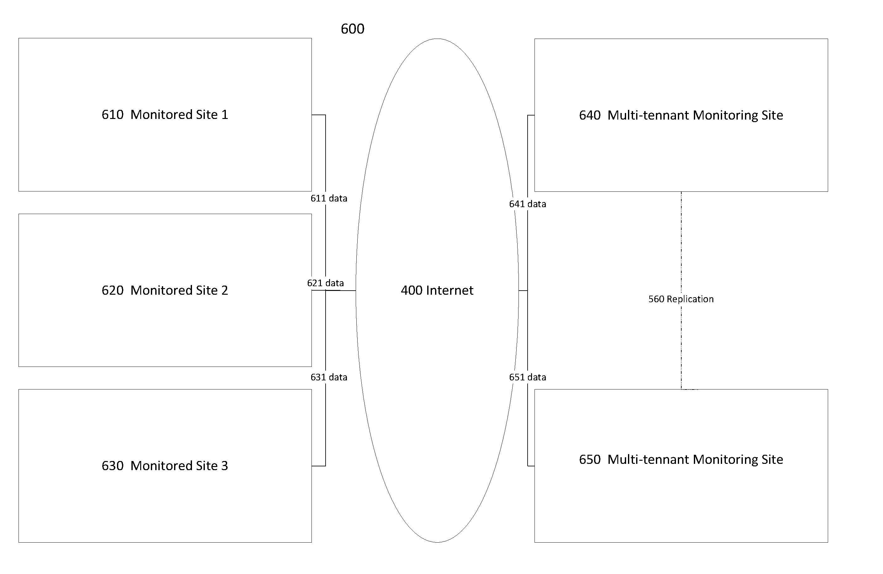
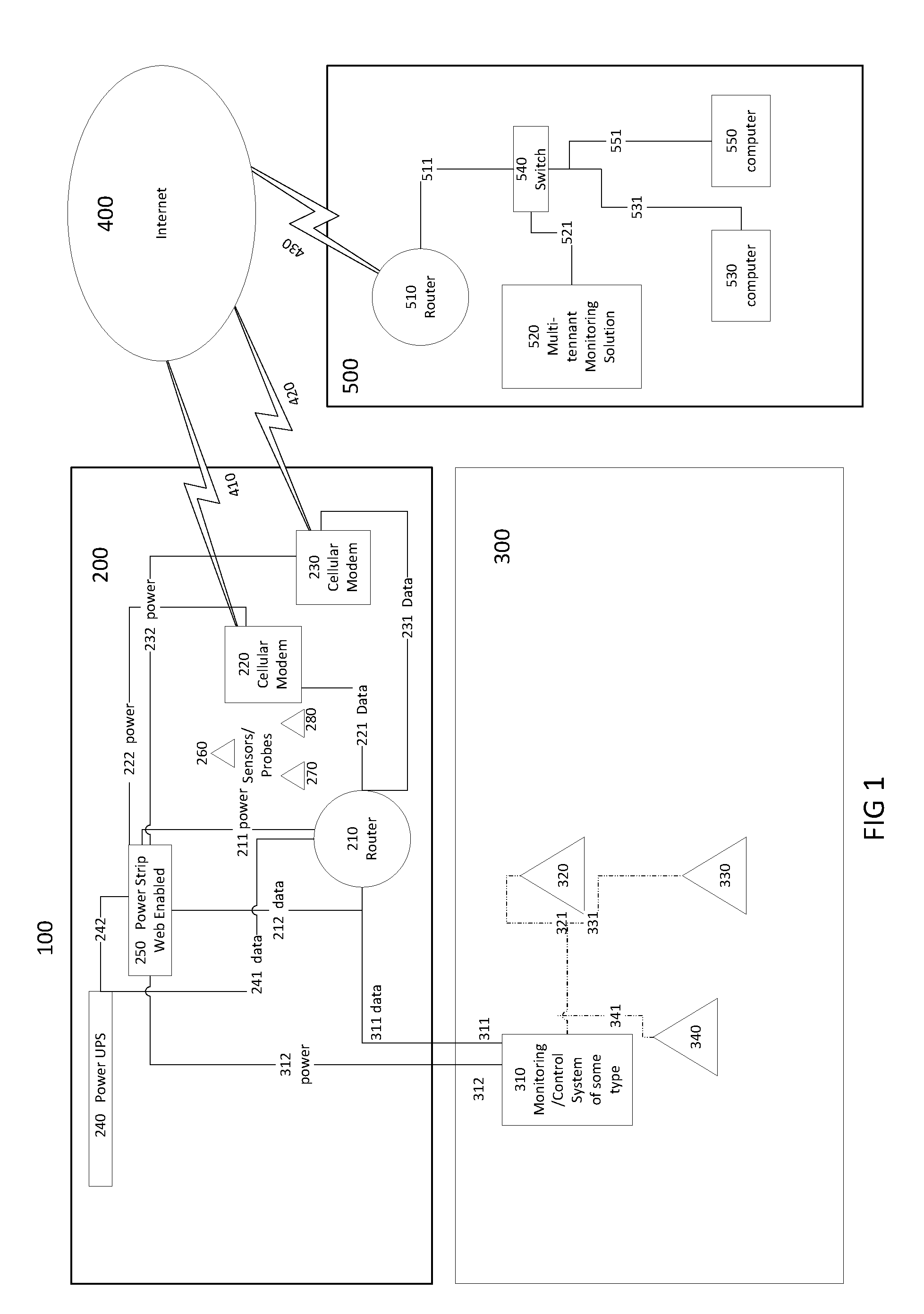
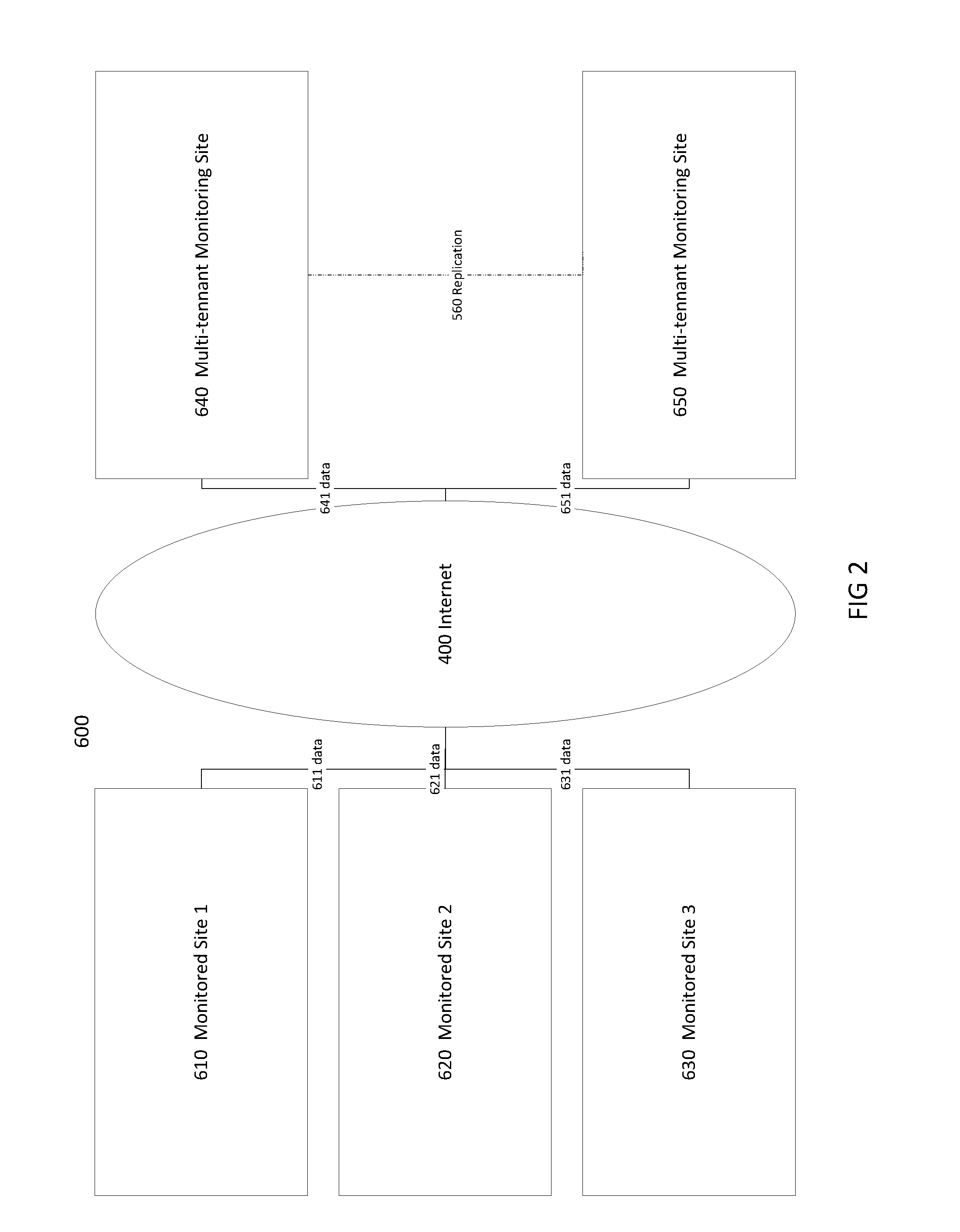
[0026]The claimed subject matter is now described with reference to the drawings. In the following description, for purposes of explanation, numerous specific details are set forth in order to provide a thorough understanding of the claimed subject matter. It may be evident; however, that the claimed subject matter may be practiced with or without any combination of these specific details, without departing from the spirit and scope of this invention and the claims.

[0027]Illustrative embodiments of the system and method of use of the present application are provided below. It will of course be appreciated that in the development of any actual embodiment, numerous implementation-specific decisions will be made to achieve the developer's specific goals, such as compliance with system-related and business-related constraints, which will vary from one implementation to another. Moreover, it will be appreciated that such a development effort might be complex and time-consuming, but would...


PUM


Abstract

A method for assembling, integrating and utilizing common network elements including routers, modems, computers and software routines for maintaining and manipulating operating functions of remotely deployable controller systems, sensors, values, relays and other electro-mechanical devices to function as an inverse proactive status monitor and management system with reporting and remote access functions in a multi-tenant operating environment.

Description

CROSS-REFERENCE TO RELATED APPLICATION35 USC §119(e)[0001]Priority is claimed from U.S. provisional application for patent 62 / 183,430, filed on Jun. 23, 2015, which is hereby incorporated by reference. This application may be related to the present application, or may have some drawings and / or disclosure in common.FIELD OF INVENTION[0002]The present invention relates generally to remote monitoring systems.BACKGROUND OF INVENTION[0003]Monitoring, control and management systems are capable of monitoring and interactively controlling a wide variety of different devices or device integrated systems. These systems typically receive or detect events (either timed, random or exception based) sent over wired and / or wireless networks from monitoring devices, sensors or systems including manual systems operated by humans. There are a great number of monitoring devices that can monitor virtually anything (e.g. temperature, pressure, electrical voltages and currents, humidity, flow volume, data...

Claims


Application Information

Patent Timeline
IPC IPC(8): G05B19/4155G05B19/406H04L29/08
CPCG05B19/4155G05B2219/31396G05B19/406H04L67/125
Inventor GOODRICH, GREG
Owner GOODRICH GREG
Learn More